Tracking error detection apparatus

a technology of error detection and optical recording, which is applied in the direction of digital recording/reproducing, data recording, instruments, etc., can solve the problems of not being suited to be integrated with neighboring digital signal processing units, difficult to cope with speedup of optical recording/reproduction apparatus or increase in recording density on optical disc, etc., to achieve further reduction of power consumption, and power consumption can be further reduced

Inactive Publication Date: 2006-03-14
PANASONIC CORP
View PDF22 Cites 14 Cited by
  • Summary
  • Abstract
  • Description
  • Claims
  • Application Information

AI Technical Summary

Benefits of technology

[0032]The present invention is made to solve the above-described problems and has for its object to provide a tracking error detection apparatus that can reduce power consumption by lowering the operation rates of the respective processing units when generating a tracking error signal.

Problems solved by technology

However, when the processing speed of the optical recording / reproduction apparatus is increased, since the channel rate of the read data varies, the required amount of delay varies significantly, and therefore, optimization of the delay circuit must be carried out.
As described above, in the conventional tracking error detection method using analog signal processing, it is difficult to cope with speedup of the optical recording / reproduction apparatus or an increase in the recording density on the optical disc.
Further, since the conventional tracking error detection apparatus includes many processing units for analog signal processing, it is not suited to be integrated with neighboring digital signal processing units.
Finally, the phase error signal is subjected to band restriction by the LPF 11, resulting in a tracking error signal of a frequency band that is required for tracking servo control.
However, when the pickup moves toward the outer circumference of the disc, since the channel rate becomes higher than that at the inner circumference while the sampling clock is the fixed clock corresponding to the inner circumference, the interval of sampling performed on the read data is undesirably increased.
In the tracking error detection apparatus employing digital signal processing, since the tracking error signal is obtained from the point number of interpolation data which are obtaining by interpolating the sampling data, the interval of the interpolation data is increased relatively to an increase in the sampling interval, whereby the amplitude of the obtained tracking error signal varies undesirably.
In the above-described tracking error detection apparatus employing digital signal processing, although the read clock, which is generated in the read channel unit as an operation clock for the tracking error detection apparatus, is used to cope with the CAV reproduction, when the reproduction speed of the drive increases, the read clock also increases in proportion to the reproduction speed, resulting in an increase in power consumption of the tracking error detection apparatus.

Method used


Image

  • Tracking error detection apparatus
  • Tracking error detection apparatus
  • Tracking error detection apparatus

Examples


embodiment 1

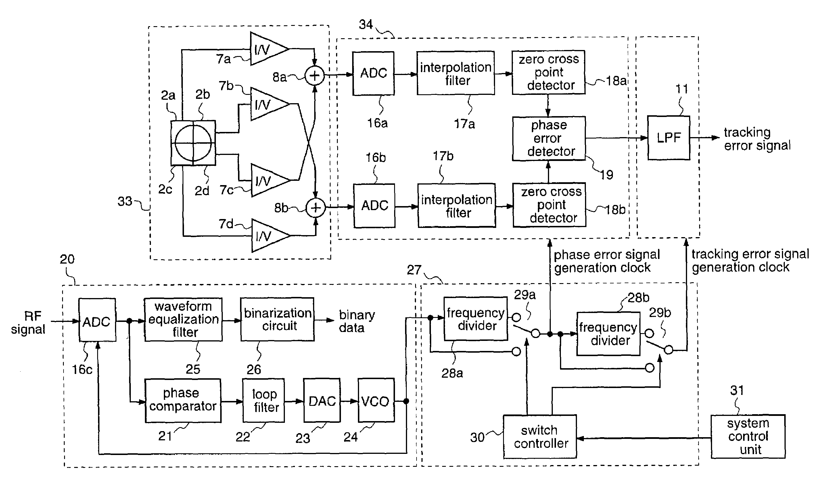
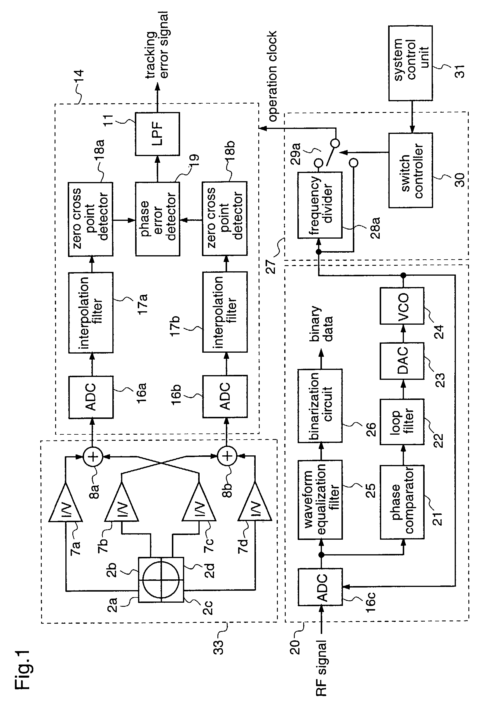
[0064]Hereinafter, a tracking error detection apparatus according to a first embodiment of the present invention will be described with reference to FIG. 1.

[0065]FIG. 1 is a block diagram illustrating a tracking error detection apparatus according to the first embodiment.

[0066]With reference to FIG. 1, the tracking error detection apparatus comprises an optical signal detection unit 33 including a photoreceptor 2, a tracking error detection unit 14, a read channel unit 20, a clock control unit 27, and a system control unit 31.

[0067]The optical signal detection unit 33 comprises a photoreceptor 2 which is divided into four elements 2a, 2b, 2c, and 2d, current-to-voltage converters 7a, 7b, 7c, and 7d, and adders 8a and 8b. The tracking error detection unit 14 comprises A / D converters 16a and 16b, interpolation filters 17a and 17b, zero cross point detectors 18a and 18b, a phase error detector 19 for calculating a phase error signal, and a low-pass filter (LPF)[0068]11. The read channe...

embodiment 2

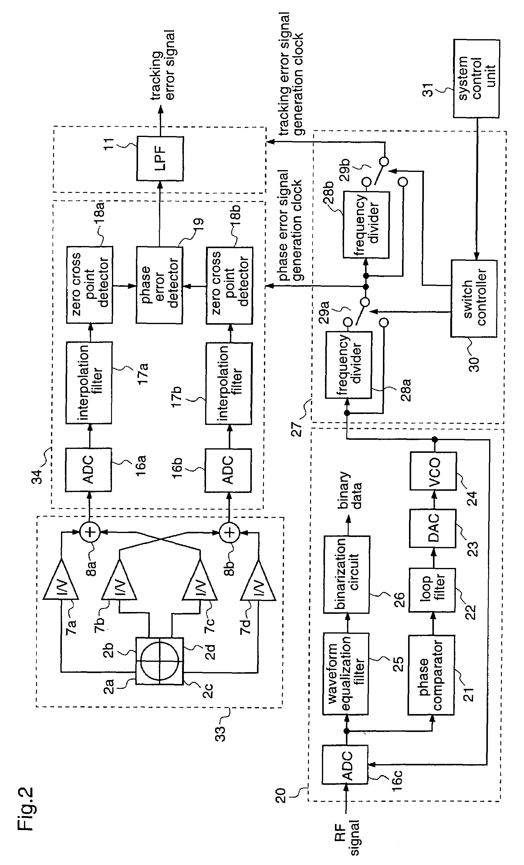
[0080]Hereinafter, a tracking error detection apparatus according to a second embodiment of the present invention will be described with reference to FIG. 2.

[0081]FIG. 2 is a block diagram illustrating the construction of a tracking error detection apparatus according to the second embodiment of the invention.

[0082]With reference to FIG. 2, the tracking error detection apparatus comprises an optical signal detection unit 33 including a photoreceptor, a phase error detection unit 34, a LPF 11, a read channel unit 20, a clock control unit 27, and a system control unit 31. Since the tracking error detection apparatus according to this second embodiment is identical to the apparatus according to the first embodiment except the construction of the clock control unit 27, the same constituents as those described for the first embodiment are given the same reference numerals to omit the description thereof.

[0083]The clock control unit 27 shown in FIG. 2 comprises a first-stage frequency div...

embodiment 3

[0092]Hereinafter, a tracking error detection apparatus according to a third embodiment of the present invention will be described with reference to FIGS. 3 and 4(a)–(f).

[0093]FIG. 3 is a block diagram illustrating the construction of a tracking error detection apparatus according to the third embodiment.

[0094]In FIG. 3, the tracking error detection apparatus comprises an optical signal detection unit 33 including a photoreceptor, a tracking error detection unit 14, a read channel unit 20, a clock control unit 27, and a servo control unit 32. Since the tracking error detection apparatus according to this third embodiment is identical to the apparatus according to the first embodiment except the construction of the clock control unit 27 and the servo control unit 32, the same constituents as those described for the first embodiment are given the same reference numerals to omit the description thereof.

[0095]The clock control unit 27 comprises a switch 29c and a switch controller 30.

[0...


PUM

PropertyMeasurementUnit
phase erroraaaaaaaaaa
phaseaaaaaaaaaa
rotation speedaaaaaaaaaa

Abstract

A tracking error detection apparatus includes a phase error detection unit for detecting a phase error of an output signal according to the amount of reflected light that is obtained when a light beam is applied to an information recording medium and a low-band pass unit for performing band restriction to obtain a tracking error signal from the phase error signal. The tracking error detection apparatus also includes a clock generation unit for generating a clock and a clock control unit having a frequency divider for generating a frequency-divided clock of the clock that is generated by the clock generation unit, wherein the clock control unit uses the frequency-divided clock as an operation clock for the tracking error detection apparatus. Therefore, the operation rate of each unit when generating a tracking error signal can be reduced, whereby a reduction in power consumption is achieved.

Description

FIELD OF THE INVENTION[0001]The present invention relates to an optical recording / reproduction apparatus for optically recording or reproducing information on / from an information storage medium, and a tracking error detection apparatus included in an optical pickup.BACKGROUND OF THE INVENTION[0002]In recent years, there has been employed a phase difference detection method as a method for obtaining a tracking control signal from an optical disc on which information is recorded by concave and convex pits, as typified by a CD (Compact Disc) and a DVD (Digital Video Disc).[0003]This method utilizes a phenomenon in which, when a light spot applied to an information recording surface of an optical disc passes over an information pit, an image (diffraction pattern) of the information pit on a photoreceptor changes due to a deviation of the light spot from the center of the information pit. To be specific, the photoreceptor is divided into plural elements in the direction along the track l...

Claims


Application Information

Patent Timeline
Patent Type & Authority Patents(United States)
IPC IPC(8): G11B7/095G11B20/10G11B7/085G11B7/09
CPCG11B7/0906G11B7/085
Inventor HIRATSUKA, TAKASHIGE
Owner PANASONIC CORP
Why Eureka
Try Eureka