Method and apparatus for the delivery of samples to a chemical sensor array

a sensor array and sample technology, applied in the field of chemical sensor array systems, can solve the problems of small changes in the electrical resistance of the layers of the sensor array, the inability to create large saw arrays with multiple sensor sites, and the difficulty of expanding into more complex analysis

Inactive Publication Date: 2006-04-04
THE UNIV OF TEXAS SYST
View PDF198 Cites 44 Cited by
  • Summary
  • Abstract
  • Description
  • Claims
  • Application Information

AI Technical Summary

Benefits of technology

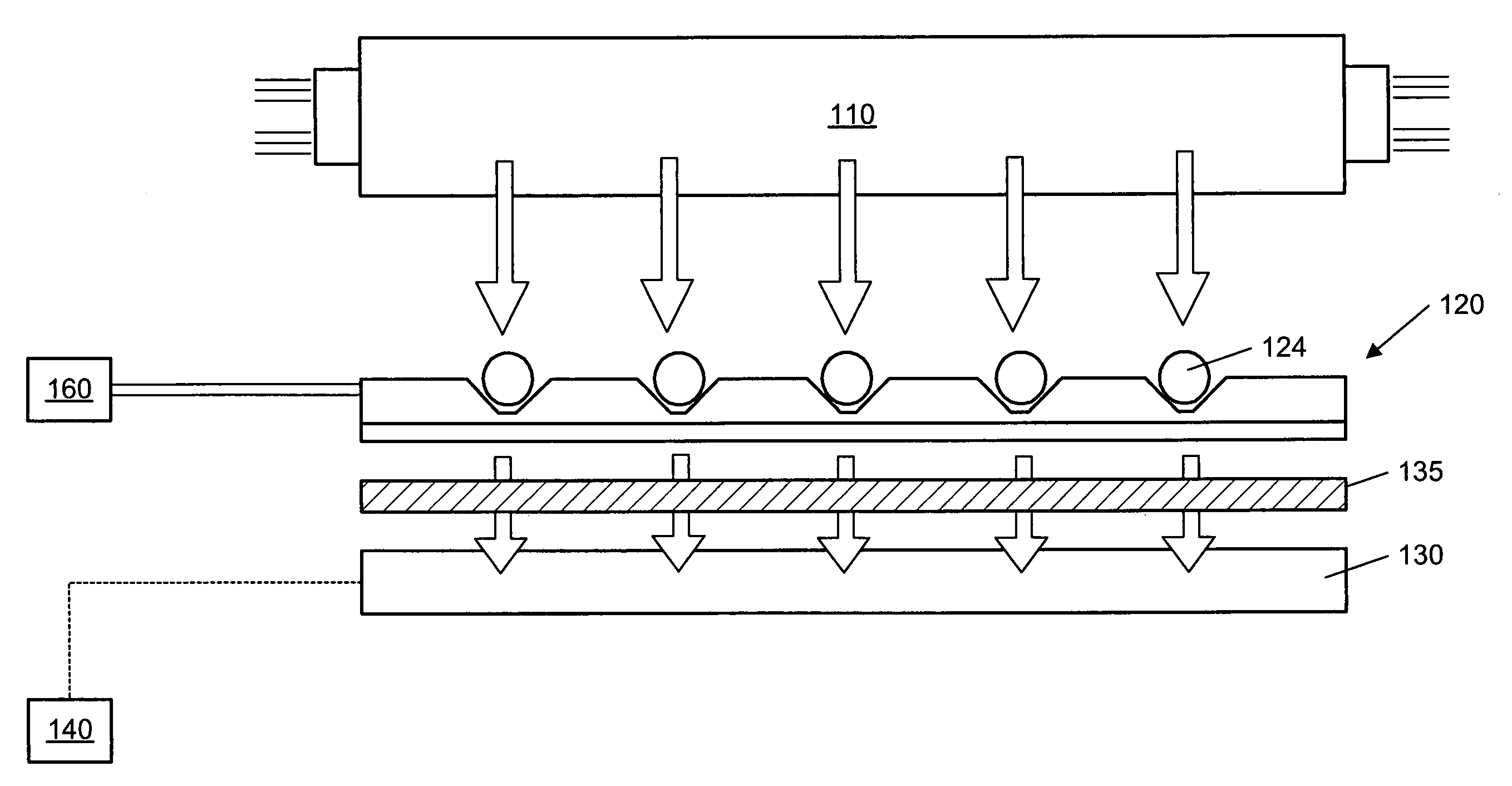
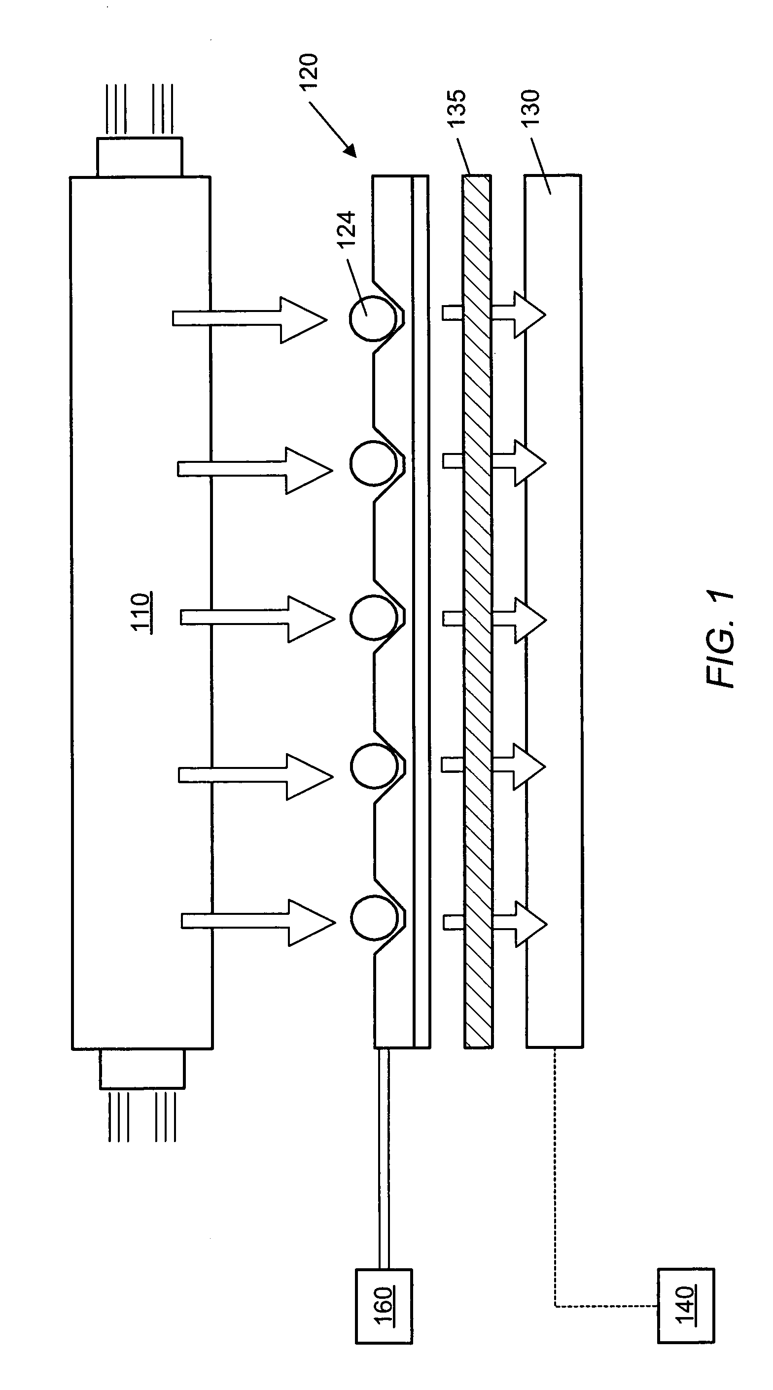
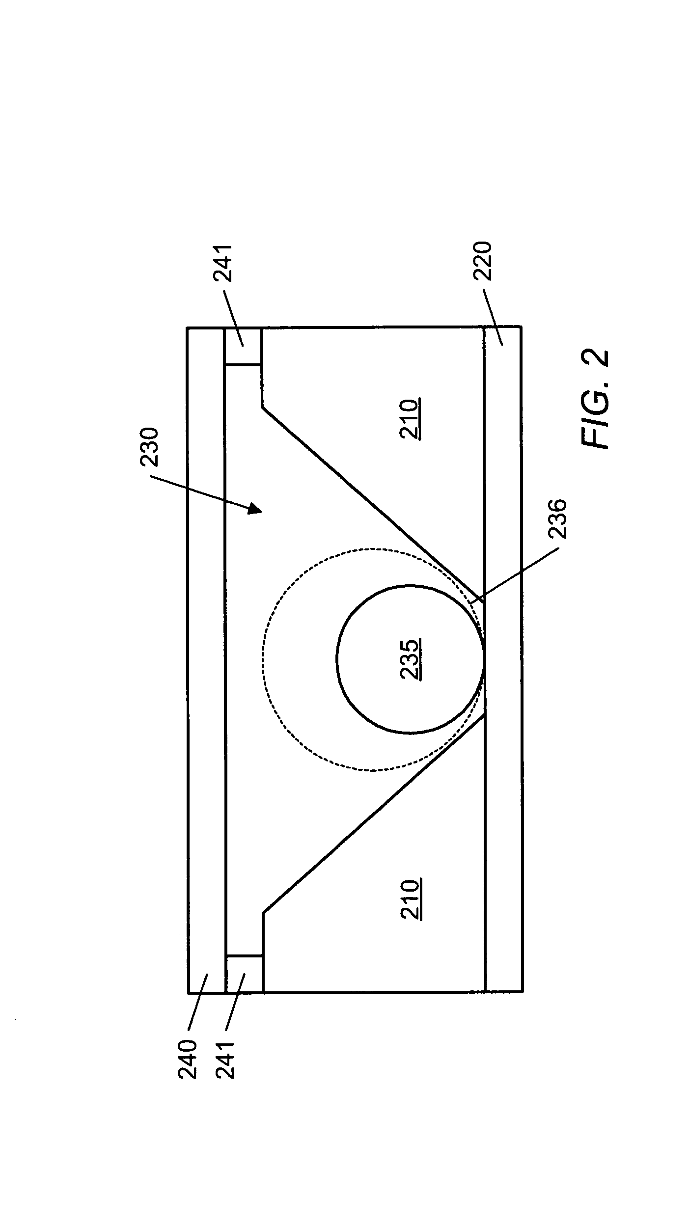
[0017]Herein we describe a system and method for the analysis of a fluid containing one or more analytes. The system may be used for either liquid or gaseous fluids. The system, in some embodiments, may generate patterns that are diagnostic for both the individual analytes and mixtures of the analytes. The system in some embodiments, is made of a plurality of chemically sensitive particles, formed in an ordered array, capable of simultaneously detecting many different kinds of analytes rapidly. An aspect of the system is that the array may be formed using a microfabrication process, thus allowing the system to be manufactured in an inexpensive manner.
[0021]In an embodiment, the optical detector may be integrated within the bottom of the supporting member, rather than using a separate detecting device. The optical detectors may be coupled to a microprocessor to allow evaluation of fluids without the use of separate detecting components. Additionally, a fluid delivery system may also be incorporated into the supporting member. Integration of detectors and a fluid delivery system into the supporting member may allow the formation of a compact and portable analyte sensing system.

Problems solved by technology

Arrays based on SAW crystals yield extremely sensitive responses to vapor, however, engineering challenges have prevented the creation of large SAW arrays having multiple sensor sites.
Additionally, limited chemical diversity and the lack of understanding of the molecular features of such systems makes their expansion into more complex analysis difficult.
When these sensors are exposed to volatile reagents, some of the volatile reagents adsorb into the polymer layers, leading to small changes in the electrical resistance of these layers.
Although the above described electronic nose provides an impressive capability for monitoring volatile reagents, the system possesses a number of undesirable characteristics that warrant the development of alternative sensor array systems.
Moreover, the electronic nose systems are expensive (e.g., the Aromascan system costs about $50,000 / unit) and bulky (≧1 ft3).
Furthermore, the functional elements for the currently available electronic nose are composed of conductive polymer systems which possess little chemical selectivity for many of the analytes which are of interest to the military and civilian communities.
However, the LATs lack the ability to be utilized for multiple, real time analyte detection schemes as the nature of the response intrinsically depends on a cooperative effect of the entire collection of microspheres.
Although quite promising for the detection of DNA fragments, these arrays are generally not designed for non-DNA molecules, and accordingly show very little sensitivity to smaller organic molecules.
Moreover, while a number of prototype DNA chips containing up to a few thousand different nucleic acid probes have been described, the existing technologies tend to be difficult to expand to a practical size.
As a result, DNA chips may be prohibitively expensive for practical uses.
Methods for manufacturing large numbers of reproducible sensors, however, has yet to be developed.
Moreover, no methods for acquisitions of data streams in a simultaneous manner are commercially available with this system.
Optical alignment issues may also be problematic for these systems.
Since the identification and isolation of the appropriate antibodies is time consuming, these techniques are limited to a single agent per testing module and there is no opportunity to evaluate the amount of agent present.
The fastest methods are generally agglutination reactions, but these methods are less sensitive due to difficulties in visual interpretation of the reactions.
These detection schemes do not, however, appear to allow the simultaneous detection of multiple analytes on a single detector platform.
As with antibody-antigen reactions this approach has not been developed for the simultaneous detection of multiple analytes.
However, the current limitations of these testing methods are related to delays caused by specimen preparation, amplification, and detection.

Method used


Image

  • Method and apparatus for the delivery of samples to a chemical sensor array
  • Method and apparatus for the delivery of samples to a chemical sensor array
  • Method and apparatus for the delivery of samples to a chemical sensor array

Examples


examples

1. The Determination of pH Using a Chemically Sensitive Particle.

[0157]Shown in FIG. 15 is the magnitude of the optical signal transmitted through a single polymer particle derivatized with o-cresolphthalein. Here, a filter is used to focus the analysis on those wavelengths which the dye absorbs most strongly (i.e., about 550 nm). Data is provided for the particle as the pH is cycled between acid and basic environments. In acidic media (i.e., at times of 100–150 seconds and 180–210 seconds), the particle is clear and the system yields large signals (up to greater than 300,000 counts) at the optical detector. Between times of 0–100 and 150–180 seconds, the solution was made basic. Upon raising the pH (i.e., making the solution more basic), the particle turns purple in color and the transmitted green light is greatly diminished. Large signal reductions are recorded under such circumstances. The evolution of the signal changes show that the response time is quite rapid, on the order of...


PUM


Abstract

A system for the rapid characterization of multi-analyte fluids, in one embodiment, includes a light source, a sensor array, and a detector. The sensor array is formed from a supporting member into which a plurality of cavities may be formed. A series of chemically sensitive particles are, in one embodiment positioned within the cavities. The particles may be configured to produce a signal when a receptor coupled to the particle interacts with the analyte. Using pattern recognition techniques, the analytes within a multi-analyte fluid may be characterized.

Description

PRIORITY CLAIM[0001]This application claims priority to U.S. Provisional Application No. 60 / 144,436 entitled “DETECTION SYSTEM BASED ON AN ANALYTE REACTIVE PARTICLE,” filed Jul. 16, 1999, U.S. Provisional Application No. 60 / 144,435 entitled “GENERAL SIGNALING PROTOCOLS FOR CHEMICAL RECEPTORS IN IMMOBILIZED MATRICES,” filed Jul. 16, 1999, and U.S. Provisional Application No. 60 / 144,126 entitled “METHOD AND APPARATUS FOR THE DELIVERY OF SAMPLES TO A CHEMICAL SENSOR ARRAY,” filed Jul. 16, 1999.STATEMENT REGARDING FEDERALLY SPONSORED RESEARCH OR DEVELOPMENT[0002]Research leading to this invention was federally supported, in part, by grant No. 1R01GM57306-01 entitled “The Development of an Electronic Tongue” from the National Institute of Health and the U.S. Government has certain rights to this invention.BACKGROUND OF THE INVENTION[0003]1. Field of the Invention[0004]The present invention relates to a method and device for the detection of analytes in a fluid. More particularly, the inv...

Claims


Application Information

Patent Timeline
IPC IPC(8): C12M1/34G01N33/543
CPCG01N21/05G01N21/6428G01N21/6452G01N21/6486G01N21/6454G01N2021/056G01N2021/0346
Inventor MCDEVITT, JOHN T.ANSLYN, ERIC V.SHEAR, JASON B.NEIKIRK, DEAN P.BORICH, DAMON V.
Owner THE UNIV OF TEXAS SYST
Why Eureka
Try Eureka