Infrared leak detector

a leak detector and infrared technology, applied in the field of gas leak detection, can solve the problems of short sensor life, health and environment threats, and problems with these technologies, and achieve the effects of eliminating mechanical and or electrical devices, eliminating noise, and eliminating extra signal processing

Inactive Publication Date: 2006-04-04
TWIN RIVERS ENG
View PDF14 Cites 47 Cited by
  • Summary
  • Abstract
  • Description
  • Claims
  • Application Information

AI Technical Summary

Benefits of technology

[0013]A fourth objective of the invention is to provide an infrared leak detector having a long sensor life that does not become easily degraded by exposure to large leaks or other reactive gases.
[0024]The output of these 2 parallel detectors can be buffered by a JFET. An IR optical filter is just in front of the IR detector, to allow the detector to only “see” the narrow band wavelengths selected for maximum, unique interaction with the Refrigerant. An optical filter is typically placed in the beam-line before the IR interaction tube, to eliminate both large and small wavelength radiation from entering the gas interaction area. This eliminates the chance for this excess energy, out of the band of interest, to interact with foreign gases (e.g., water vapor, CO2) such that re-emission into the band of interest can create noise and false signals.

Problems solved by technology

However, using the detector to analyze certain types of gases such as refrigerants, and the like, raises safety and environmental concerns.
This application is important, as leaking refrigerant gas can pose a threat to both health and the environment.
However, problems existed with these technologies.
For example, short sensor life and false alarms have been usual problematic results.
Although infrared technology has existed for many years, infrared technology has not been previously used for leak detection applications for many reasons.
For example, manufacturing costs would have made the use of infrared technology too expensive to be used as a leak detector.
However, there are known problems with the “closed path” monitors.
For example, analysis is complicated by very little light energy being absorbed by low gas concentrations, substantial low frequency noise present in the analysis system and optical losses associated with typical optical pathways.
However, there are problems with these solutions.
Broadband light sources use a filament to produce spectral emission and accordingly, electronic modulation thereof at high frequencies is impractical.
The filaments require too much time to heat up and cool down for high-frequency modulation.
Unfortunately, mechanical choppers consume significant energy, decrease instrument reliability and increase the complexity, size and weight of instruments that they are incorporated within.
However, these solutions increase the size, cost and / or weight of the instruments to which they are applied.

Method used


Image

  • Infrared leak detector
  • Infrared leak detector
  • Infrared leak detector

Examples


Embodiment Construction

[0037]Before explaining the disclosed embodiments of the present invention in detail it is to be understood that the invention is not limited in its application to the details of the particular arrangement shown since the invention is capable of other embodiments. Also, the terminology used herein is for the purpose of description and not of limitation.

[0038]For the invention, “air” can refer to a gaseous sample that may or may not contain any molecules of interest to the user. “Refrigerant” can refer to molecules of the gas with is of interest to the user, i.e., to be detected, but could in some applications be other refrigerants or other compounds of interest such as Methane, gasoline, and the like.

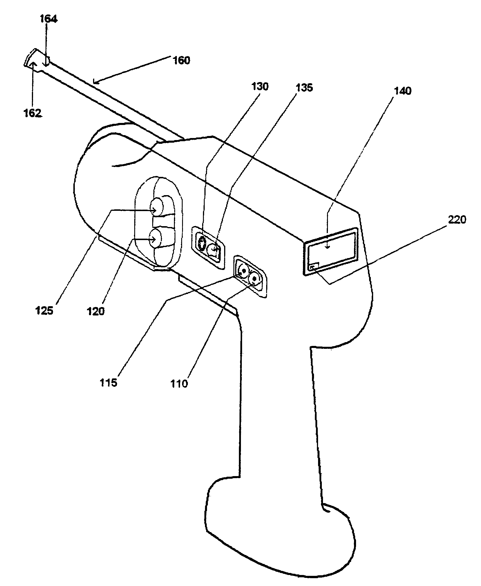
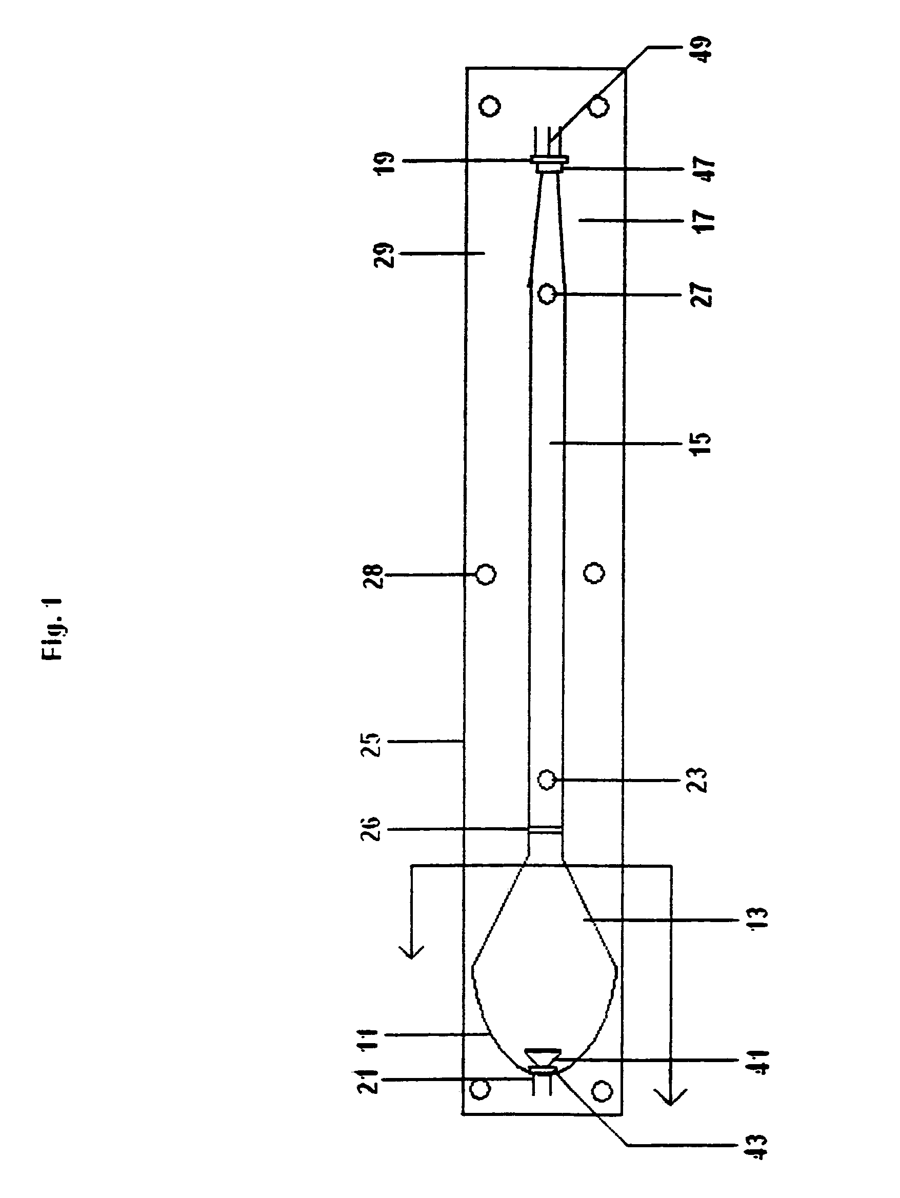
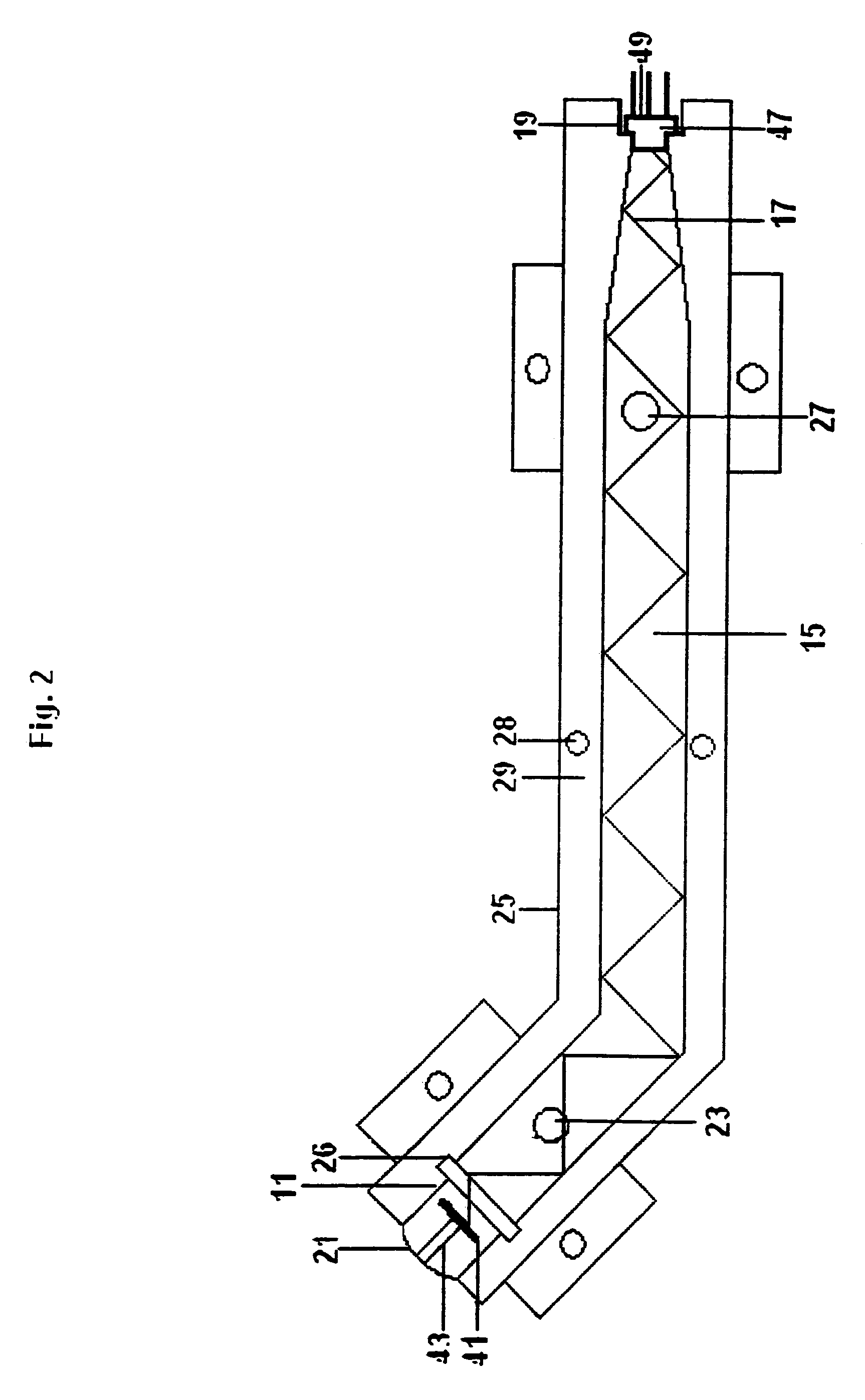
[0039]The novel leak detector can be comprised of an infrared (IR) chamber, an air pump to draw in a sample, and electronics to process the signal. The IR chamber can contain an IR emitter, IR filters, an IR sensor, and a reaction tube where the sample air interacts with the IR beam.

[00...


PUM

PropertyMeasurementUnit
response timeaaaaaaaaaa
flow rateaaaaaaaaaa
weightaaaaaaaaaa

Abstract

Leak detector using infrared for identifying the presence and concentration of a selected gas. For detection, radiation from an infrared emitter penetrates the sample, which is analyzed spectrally, and results in a wave length-specific signal being generated at the output. By controlling the optical filter, the radiation is controlled at a selected wavelength, to ensure coverage of all selected compounds. For refrigerants, the selected wavelength can be between approximately 8 to approximately 10 microns. This wavelength obscures other signals, thus minimizing false alarms. The leak detector has a faster time with no adverse impacts on the accuracy of the compound being detected. To further minimize false alarms and to ensure that the emitter does not come in contact with the gas, an additional filter can be used. For refrigerant compounds, the filter can block out signals below approximately 6 microns. For detecting refrigerants, two filters can be used.

Description

[0001]This invention is a divisional application of U.S. patent application Ser. No. 10 / 138,399 filed May 3, 2002 now U.S. Pat. No. 6,791,088, which claims the benefit of priority to U.S. Provisional application 60 / 288,857 filed May 4, 2001.FIELD OF INVENTION[0002]This invention relates to gas leak detection and in particular to methods and devices using infrared optical chambers with circuits in a portable gas leak detector.BACKGROUND AND PRIOR ART[0003]Leak detectors have been used for many applications which include detecting the concentration of specific types of gases. However, using the detector to analyze certain types of gases such as refrigerants, and the like, raises safety and environmental concerns. For example, a leak detector can be designed to detect the concentration of refrigerant gas in surrounding ambient air. This application is important, as leaking refrigerant gas can pose a threat to both health and the environment. As used herein, the term gas refers to any g...

Claims


Application Information

Patent Timeline
Patent Type & Authority Patents(United States)
IPC IPC(8): G01J5/02G01M3/04G01N21/11G01N21/35
CPCG01M3/047G01N21/3504G01N21/11G01N2201/0221
Inventor WILLIAMS, II, WILLIAM J.DEJONG, GLENN A.
Owner TWIN RIVERS ENG
Why Eureka
Try Eureka