Radiation converter

a radiation converter and converter technology, applied in the field of radiation converters, can solve the problems of poor image representation capability, flat panel image detectors, and small distance between signal levels and noise signals, and achieve the effect of improving the dynamic range of such a radiation converter

Inactive Publication Date: 2006-04-04
SIEMENS AG
View PDF16 Cites 7 Cited by
  • Summary
  • Abstract
  • Description
  • Claims
  • Application Information

AI Technical Summary

Benefits of technology

[0013]It is an object of the invention to provide a radiation converter which can be used as universally as possible. It is a further aim to improve the dynamic range of such a radiation converter.

Problems solved by technology

The distance between the signal levels and the noise signals likewise becomes smaller, which is associated with a poorer diagnosis capability of the image representations that can be generated on the basis of these signals.
Particularly for fluoroscopy, in which only small x-ray doses are applied, the signals which can be derived from the flat panel image detector are particularly small and near the region of the noise and thus require complicated artifact corrections.
Moreover, the dynamic range of the signals which can be derived from the flat panel image detector is greatly restricted.
Operation of such flat panel image detectors in different operating modes, such as fluoroscopy and radiography, which differ by dose factors of 100–1000, requires a high computation complexity.

Method used


Image

  • Radiation converter
  • Radiation converter

Examples


Embodiment Construction

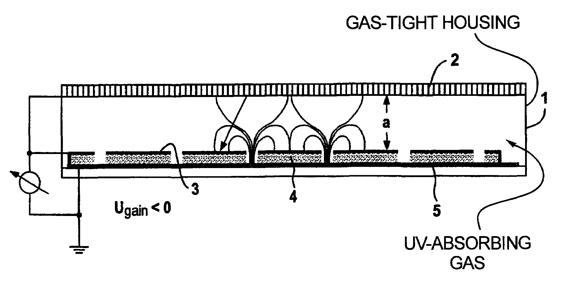
[0023]The radiation converter shown in FIG. 1 has a gas-tight housing 1 with a radiation absorber 2, which converts radiation into light photons. The radiation absorber 2 is either embodied as a separate part or arranged outside the housing 1 in the region of a first side. The radiation absorber 2 is composed of a scintillator material, preferably CsI:Na in a needle structure, the needles being directed in the direction of a photocathode 3.

[0024]The photocathode 3 is arranged at a distance a of about 50 μm away from the radiation absorber 2 and is formed as a layer, preferably produced from copper, on a perforated polyimide film 4. The polyimide film 4 acts as an electron multiplier and is applied to an electron detector 5. The electron detector 5 preferably has a pixel structure and converts the impinging electrons into electrical signals which can be derived by means of suitable known measures, for example an electrical line, and which enable an image representation on a display d...


PUM


Abstract

A radiation converter has a radiation absorber for generating photons dependent on the intensity of incident x-ray radiation, a photocathode arranged downstream of the radiation absorber in the radiation propagation direction at a distance therefrom and serving for generating electrons dependent on the photons emerging from the radiation absorber, a device for accelerating the electrons emerging from the photocathode onto an electron detector for generating electrical signals dependent on the impinging electrons, an electron multiplier arranged between the photocathode and the electron detector, the electrons emerging from the photocathode being multiplied by the electron multiplier.

Description

BACKGROUND OF THE INVENTION[0001]1. Field of the Invention[0002]The present invention is directed to a radiation converter of the type suitable for use in an x-ray system.[0003]2. Description of the Prior Art[0004]German OS 33 32 648 discloses a radiation converter embodied as an image intensifier. Such image intensifiers have an input window with a radiation absorber for generating light photons in a manner dependent on the radiation intensity of impinging radiation. Arranged downstream of the radiation absorber is a photocathode which generates electrons in a manner dependent on the light photons emerging from the radiation absorber. The electrons are accelerated onto an electron receiver by an electrode system. In the case of the image intensifier, the electron receiver is embodied as an output screen which generates light photons dependent on the impinging electrons.[0005]U.S. Pat. No. 5,369,268 discloses an x-ray detector in which the photocathode is applied on a radiation abso...

Claims


Application Information

Patent Timeline
Patent Type & Authority Patents(United States)
IPC IPC(8): H01J40/18G21K4/00G01T1/00G01T1/20G01T1/28H01J31/49H01J43/06H01J43/28H04N5/32
CPCH01J31/49H01J2231/501H01J2231/50068H01J2231/50036
Inventor FUCHS, MANFREDHELL, ERICHKNUPFER, WOLFGANGMATTERN, DETLEF
Owner SIEMENS AG
Why Eureka
Try Eureka