Solid electrolytic capacitor

a technology of electrolytic capacitors and solids, which is applied in the direction of fixed capacitors electrical apparatus casings/cabinets/drawers, etc., can solve the problems of easy deterioration of elements, and achieve the effect of improving moisture resistance characteristics, reducing thickness, and strengthening joint strength

Inactive Publication Date: 2006-04-11
SANYO ELECTRIC CO LTD +1
View PDF7 Cites 22 Cited by
  • Summary
  • Abstract
  • Description
  • Claims
  • Application Information

AI Technical Summary

Benefits of technology

[0013]1. With the solid electrolytic capacitor 1 of the invention, the lead frames 9, 90 are each provided in the outer end face thereof with a filling portion 92 which is filled with the resin forming the housing 70. The resin thus covering the outer end faces of the lead frames 9, 90 and filling the portion 92 enhances the strength of the joint between the housing 70 and the lead frames 9, 90 even if the capacitor 1 has a reduced thickness, consequently giving improved moisture resistant characteristics to the capacitor 1.
[0013]1. With the solid electrolytic capacitor 1 of the invention, the lead frames 9, 90 are each provided in the outer end face thereof with a filling portion 92 which is filled with the resin forming the housing 70. The resin thus covering the outer end faces of the lead frames 9, 90 and filling the portion 92 enhances the strength of the joint between the housing 70 and the lead frames 9, 90 even if the capacitor 1 has a reduced thickness, consequently giving improved moisture resistant characteristics to the capacitor 1.
[0015]3. With the recess 93 covered with the resin forming the housing 70, the end portion lower face of each of the lead frames 9, 90 positioned in the cutting surface 71 of the housing 70 is prevented from being exposed, consequently precluding burrs to be formed when each lead frame is cut from projecting outward. The deburring step can therefore be dispensed with to reduce the number of steps to be included in the fabrication process. The resin covering the recess 93 also gives an increased strength to the joint between the housing 70 and each lead frame.

Problems solved by technology

If water reaches the capacitor element 2, the element is prone to deteriorate.

Method used


Image

  • Solid electrolytic capacitor
  • Solid electrolytic capacitor
  • Solid electrolytic capacitor

Examples


first embodiment

[First Embodiment]

[0034]An embodiment of the invention will be described below in detail with reference to the drawings concerned.

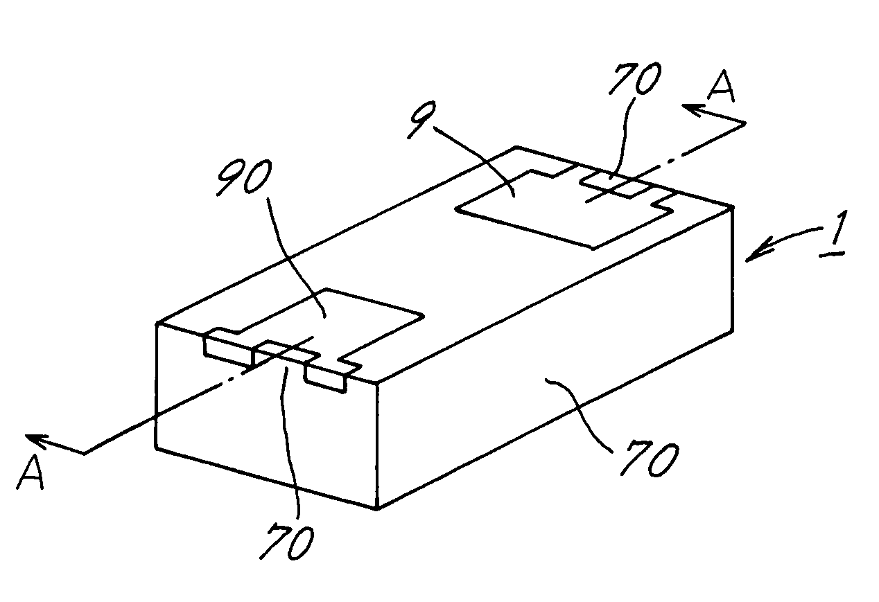
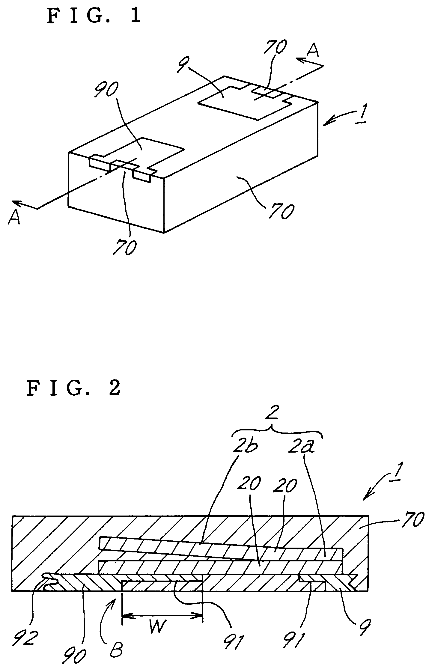
[0035]FIG. 1 is a perspective view showing a solid electrolytic capacitor 1 as turned upside down. FIG. 2 is a view in section taken along a plane containing the line A—A in FIG. 1 and showing the capacitor with its upper and lower sides positioned in reversed relation to FIG. 1.

[0036]As shown in FIG. 2, the capacitor 1 comprises a capacitor element 2 having lead frames 9, 90 attached to the lower side thereof. The capacitor element 2 is covered with a housing 70 of epoxy resin or like synthetic resin. The capacitor element 2 has the same shape as the conventional one shown in FIG. 18, and comprises superposed anode bodies 20, 20 adhered or welded to each other at their anode (2a) ends. The lead frame 90 for the cathode is provided over the lower surface of the element 2. The capacitor element 2 is in contact with the cathode-side lead frame 90 over an in...

second embodiment

[Second Embodiment]

[0055]FIG. 9 is a left side elevation of the solid electrolytic capacitor 1 of FIG. 1. The capacitor 1 is obtained by cutting the resin block 7 and metal plate 8 by a cutting tool 4 such as a dicing saw. As shown in FIG. 9, one side surface of the housing 70 is in the form of a cutting surface 71 formed by the cutting tool 4. The end portion lower faces of the lead frames 9, 90 which are positioned in the cutting surface 71 of the housing 70 are left exposed.

[0056]The cutting tool 4 cuts the metal plate 8 while in rotation, so that when the resin block 7 and the metal plate 8 are cut by the tool 4, burrs 94 are likely to project from the end portion lower faces of the lead frames 9, 90 owing to the resistance of friction between the cutting tool 4 and the metal plate 8. While capacitors 1 of the type described are mounted on a circuit board (not shown), formation of such burrs 94 will vary the height of the capacitor 1 as mounted. The step of removing burrs is the...


PUM

PropertyMeasurementUnit
lengthaaaaaaaaaa
depthaaaaaaaaaa
depthaaaaaaaaaa

Abstract

A solid electrolytic capacitor including a capacitor element having an anode body partly provided with a cathode layer, an anode-side and a cathode-side lead frame attached to a lower surface of the capacitor element, and a housing covering the lead frames and the capacitor element except lower surfaces of the lead frames. The housing covers an outer end face of each of the lead frames, the outer end face of each lead frame being provided with a filling portion filled with a resin forming the housing.

Description

FIELD OF THE INVENTION[0001]The present invention relates to solid electrolytic capacitors.BACKGROUND OF THE INVENTION[0002]FIG. 16 shows a solid electrolytic capacitor of the chip type which is well known in the art (see JP-A No. 2002-246268).[0003]The solid electrolytic capacitor 1 shown in FIG. 16 comprises a capacitor element 2 having lead frames 9, 90 attached to the bottom surface thereof. The capacitor element 2 is covered with a housing 70 of synthetic resin. The lead frames 9, 90 are bent along the housing 70. The capacitor element 2 comprises a dielectric oxide coating 21 formed on a portion of an anode body 20 which is foil of valve metal, and a cathode layer 3, a carbon layer 6 and a silver paste layer 60 successively formed over the oxide coating 21. The portion of the anode body 20 provided with the dielectric oxide coating 21 serves as a cathode 2b, and the uncoated portion of the anode body 20 not covered with the oxide coating 21 serves as an anode 2a. For the conve...

Claims


Application Information

Patent Timeline
Patent Type & Authority Patents(United States)
IPC IPC(8): H01G9/00H01G9/004H01G9/08H01G9/008H01G9/012H01G9/04H01G9/042H01G9/10H01G9/15
CPCH01G9/012H01G9/10H01G9/042Y10T29/417H01G9/008
Inventor HORIO, KAZUTOYOMATSUMOTO, TAKAYUKISAKUDA, TETSUYUKIYAMAGUCHI, MANABUAIHARA, KAZUHIROARIMORI, SHINJI
Owner SANYO ELECTRIC CO LTD
Why Eureka
Try Eureka