
Detecting natural gas pipeline failures

a technology of natural gas pipelines and failure detection, applied in the direction of optical radiation measurement, spectrophotometry/monochromators, spectrophotometry/spectrophotometry/monochromators, etc., can solve the problems of cumbersome process, cost, inconvenience, unreliable and unsafe, and add to overall costs

Inactive Publication Date: 2006-04-11
HARRIS CORP
View PDF17 Cites 20 Cited by
  • Summary
  • Abstract
  • Description
  • Claims
  • Application Information

AI Technical Summary

Benefits of technology

[0014]In many cases it is required to inspect natural gas pipelines frequently in order to determine the likelihood or development of failures since such failures can be catastrophic to the environment. In many cases these inspections are done by a ground site survey; individuals visit these locations and take measurements or other form of data on-sight. This process becomes cumbersome, costly, inconvenient, and in many cases unreliable and unsafe due to the dangers present in remote locations and to potential false interpretations due to worker fatigue and other factors. Furthermore, remote locations are frequently in mountains, deserts and forests that are difficult to reach and frequent inspection requires the placement of permanent maintenance and inspection crews adding to overall costs. It is an advantage of the present invention to provide a more effective way of determining failures in natural gas pipelines by automatically processing images captured from a remote platform. This automatic processing can include comparing with previously detected images. This automatic processing can also include algorithms and expert systems that act in a predictive manner.

Problems solved by technology

In many cases it is required to inspect natural gas pipelines frequently in order to determine the likelihood or development of failures since such failures can be catastrophic to the environment.
This process becomes cumbersome, costly, inconvenient, and in many cases unreliable and unsafe due to the dangers present in remote locations and to potential false interpretations due to worker fatigue and other factors.
Furthermore, remote locations are frequently in mountains, deserts and forests that are difficult to reach and frequent inspection requires the placement of permanent maintenance and inspection crews adding to overall costs.

Method used


Image

  • Detecting natural gas pipeline failures
  • Detecting natural gas pipeline failures
  • Detecting natural gas pipeline failures

Examples


Embodiment Construction

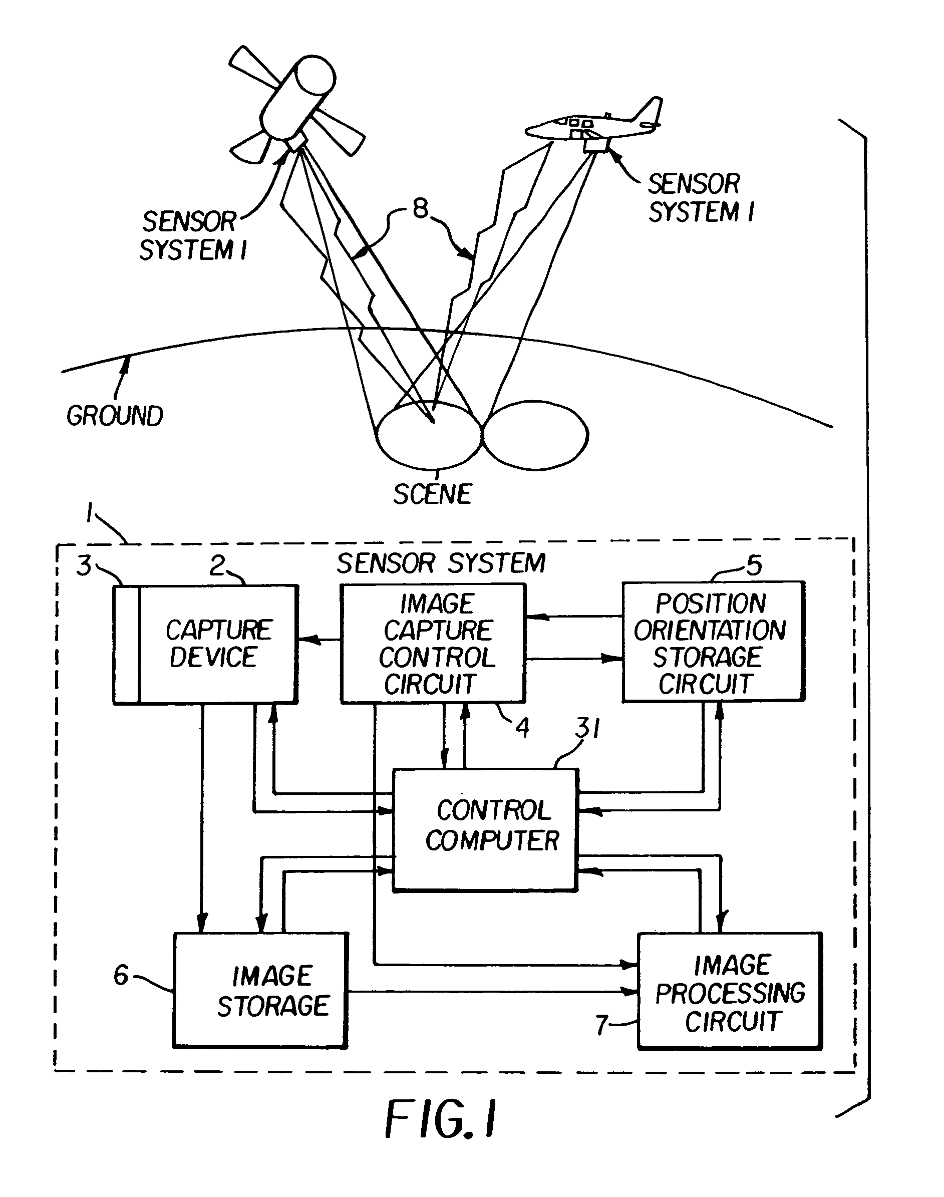
[0022]A sensor system 1 is employed in the capturing of images in order to identify material failures in a natural gas pipeline. Images of the ground containing natural gas pipelines are captured by a remote platform by this sensor system 1. Sequential images may be captured in digital form and either stored in the remote platform (for example, an aerial or satellite platform) to be transferred later or transmitted via a radio link to a control ground station. The capture device 2 includes an electronic sensor, typically a, charge coupled device (CCD) or complementary metal oxide semiconductor (CMOS) imaging array that along with some imaging optics captures a sampling of the scene in electronic form. In some instances a non-imaging sensor such as a photomultiplier tube or photodiode may be employed to detect the light signal that originates from a portion of the scene. An image may be constructed by scanning the non-imaging sensor over portions of the scene. For example radar signa...


PUM

PropertyMeasurementUnit
Ramanaaaaaaaaaa
concentrationaaaaaaaaaa
specific wavelengthaaaaaaaaaa

Abstract

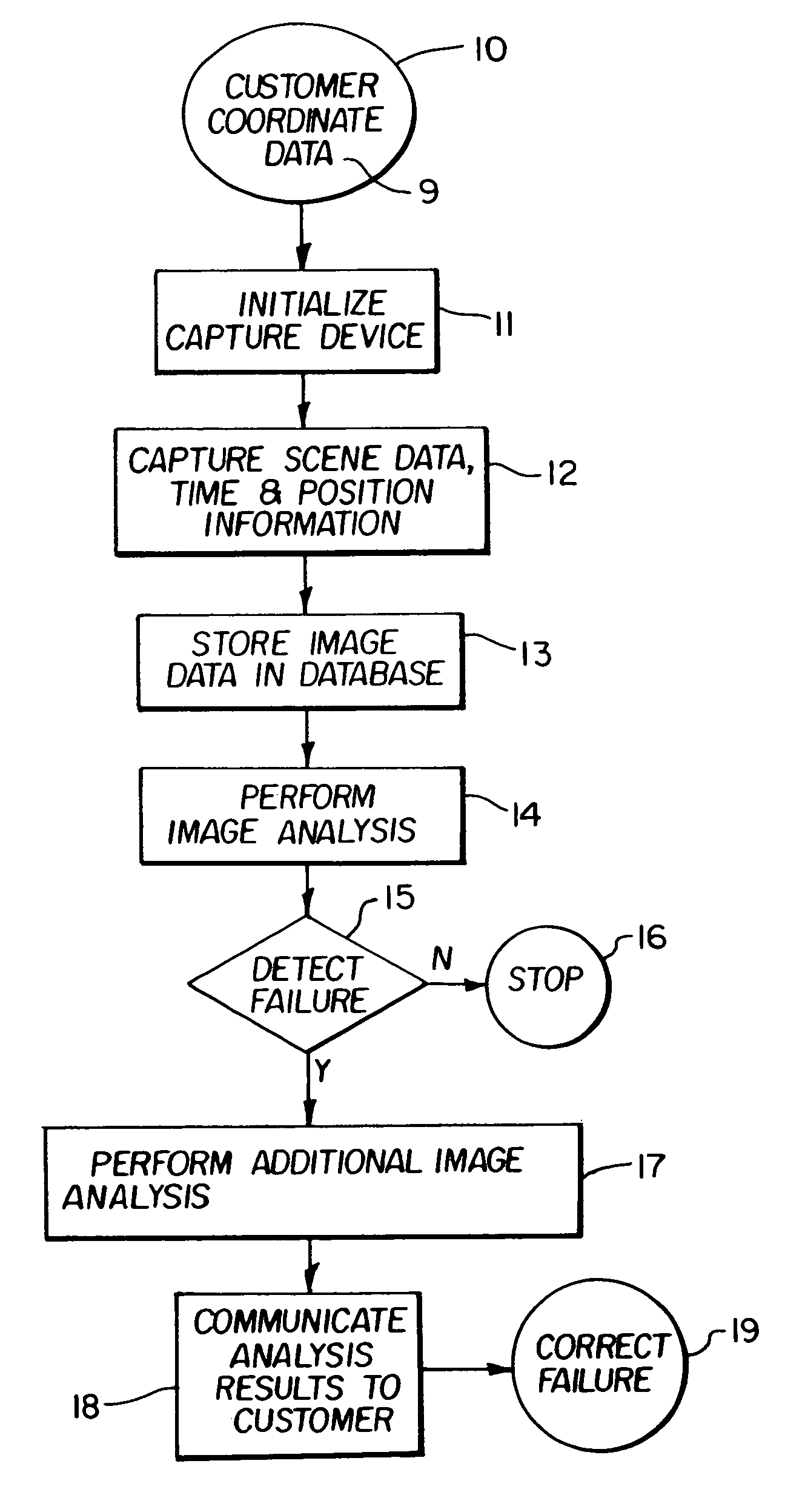
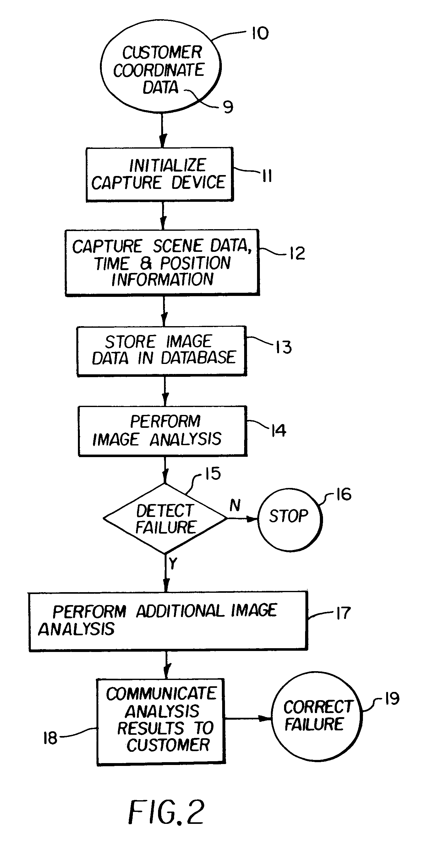
A method for detecting failures in a natural gas returning radiation from the pipeline; determining that there is a failure in the pipeline when the spectral or thermal signature indicates that there is a plume of escaping natural gas from the pipeline emitted from a failure; and indicating to a customer that a failure in the pipeline has been detected at a predetermined coordinate position.

Description

[0001]The present invention relates to remotely detecting natural gas pipeline failures.BACKGROUND OF THE INVENTION[0002]The surveillance of ground topography is well known in the art. It is frequently the case that an aircraft or a satellite includes an image capture device such as a charge coupled device (CCD). In ground surveillance it is highly desirable to detect whether there has been a material failure in a man-made object such as a road, a pipeline, an electrical grid, or other man-made structures of practical interest. When detected, a determination is made if remedial action must be taken. Often times a visual inspection of ground topography is provided by a land-based crew that traverses an area by vehicle or foot, to determine if there is a material failure. Airborne photographic systems can also be used for capturing images of adjacent areas. These images are then reviewed to determine if there is a material failure.[0003]In detecting failures in gas pipelines there is ...

Claims


Application Information

Patent Timeline
Patent Type & Authority Patents(United States)
IPC IPC(8): G01N21/00G01M3/08G01M3/02F17D5/02G01M3/00G01M3/16G01M3/18G01M3/38G01N21/31G01N21/65
CPCG01M3/005G01N21/31G01M3/38
Inventor SPOONHOWER, JOHN P.PAZ-PUJALT, GUSTAVO R.SHERIN, JANET M.GRAEN, MARTIN G.STEARNS, STEVEN V.
Owner HARRIS CORP
Learn More