

Variable capacitors, composite materials
a capacitor and capacitor technology, applied in the field of variable capacitor materials, can solve the problem of inability to load so high, and achieve the effect of enhancing dielectric constant and tunability, and variable capacitor capacitan
Inactive Publication Date: 2006-04-18
NGIMAT CO
View PDF7 Cites 15 Cited by
- Summary
- Abstract
- Description
- Claims
- Application Information
AI Technical Summary
Benefits of technology
"The patent describes a way to make variable capacitors using conductive particles embedded in insulating material. These particles can be made of materials that are semi-conductive or conductive, and they enhance the dielectric constant and make the capacitor easier to control. The conductive particles should be small and elongated, meaning they have dipoles that can be affected by an electric field. The patent also describes methods for making these conductive particles and using them in variable capacitors. The invention can be used in a variety of applications."
Problems solved by technology
The loading cannot be so high, however, that the conductive particulates form conductive pathways through the dielectric material layer (unless electrical insulative layers are provided).
Method used
View moreImage
Smart ImageViewing Examples

Examples
example
[0069]A dielectric material layer, 0.345 microns thick comprising 33 mol % Pt and 66 mol % silica was deposited on a Pt-coated silicon substrate. Platinum particulates and silica were co-deposited from separate combustion chemical vapor deposition (CCVD) flames, such CCVD flame deposition being taught in U.S. Pat. No. 5,652,021. A second electrode layer made of silver was formed on the exposed surface of the dielectric layer. The capacitance in picofarads was measured at various biasing voltages. Results are as follows:
Login to View More PUM
| Property | Measurement | Unit |
|---|---|---|
| biasing voltage | aaaaa | aaaaa |
| biasing voltage | aaaaa | aaaaa |
| electron/hole mobilities | aaaaa | aaaaa |
Abstract
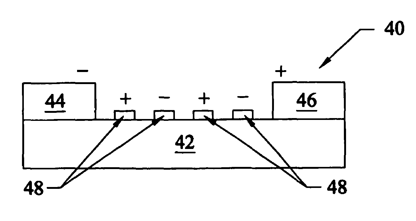
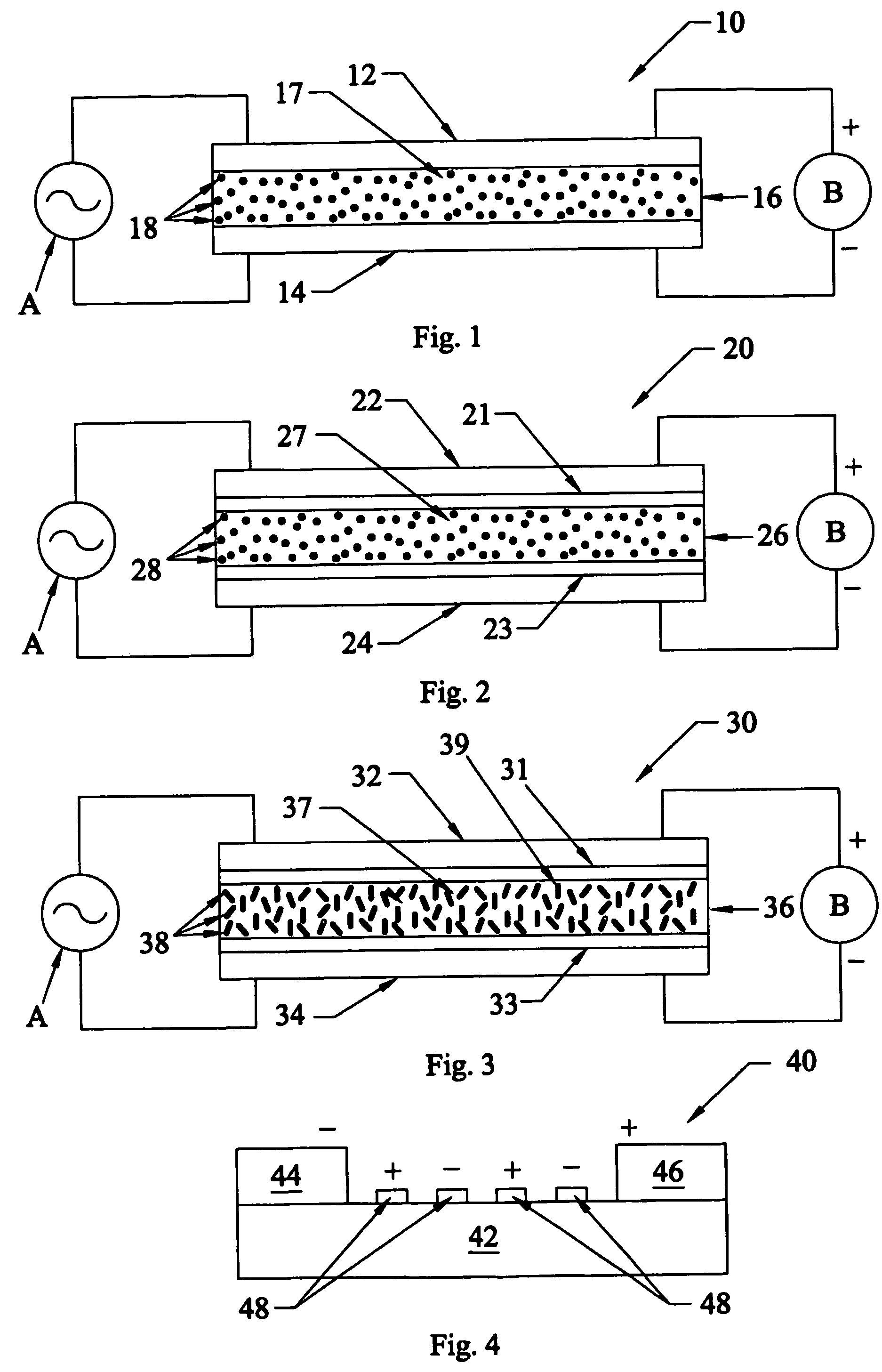
Tunable capacitors (10, 20, 30, 40) have a dielectric material (16, 26, 36, 42) between electrodes, which dielectric material comprises an insulating material (17, 27, 37, 42) and electrically conductive material, (18, 28, 38, 48) e.g., conductive nanoparticulates, dispersed therein. In certain cases, enhanced tune-ability is achieved when the dielectric material comprises elongated nanoparticulates (38). Further enhanced tune-ability may be achieved by aligning elongated particulates in an electrode-to-electrode direction. Nanoparticulates may be produced by heating passivated nanoparticulates. Passivated nanoparticulates may be covalently bound within a polymeric matrix. High bias potential device structures can be formed with preferential mobilities.
Description
[0001]The present invention is directed to capacitors that can be tuned by a biasing voltage. The present invention is also directed to novel particulates and composite materials that are useful for forming tunable capacitors.BACKGROUND OF THE INVENTION[0002]One of the issues with variable capacitor materials, dielectrics—whose dielectric permittivities change when a electric bias is applied, is that these materials must be crystalline. These materials have a perovskite structure. Many of these tunable materials have higher losses than are desired, which lowers the performance of the functional devices.[0003]In addition, these materials have large temperature coefficients of capacitance. Therefore, it is hard to keep a constant capacitance without also knowing the temperature of the system. Monitoring and feedback loops are commonly required to compensate for changes in capacitance with temperature. Therefore, decreasing the effective overall change in capacitance can eliminate the ...
Claims
Login to View More Application Information
Patent Timeline
 Patent Type & AuthorityPatents(United States)
IPC IPC(8): H01G5/00H01G4/06H01G7/06
CPCH01G7/06
InventorHUNT, ANDREW TYEOLJACA, MIODRAGFLANAGAN, SCOTTDESHPANDE, GIRISHLEE, STEINFAGUY, PETER W.
OwnerNGIMAT CO