Gas laser device and exposure apparatus using the same

a laser device and laser technology, applied in the direction of gas laser construction details, laser details, active medium materials, etc., can solve the problems of affecting the productivity of the apparatus, requiring frequent stoppage of laser operation, and requiring much time for replacement or repair of the same, so as to ensure high productivity, ensure long life, and ensure high power

Inactive Publication Date: 2006-04-18
CANON KK
View PDF47 Cites 8 Cited by
  • Summary
  • Abstract
  • Description
  • Claims
  • Application Information

AI Technical Summary

Benefits of technology

[0008]It is accordingly an object of the present invention to provide a gas laser device having a long lifetime and a high power.
[0009]It is another object of the present in

Problems solved by technology

If the lifetime of the blowing machine provided in the chamber is short, the operation of the laser has to be stopped frequently for replacement of the laser or blowing machine or for repair of the same.
In cases where the laser is used as a light source in an exposure apparatus, it largely affects the productivity of the apparatus.
Since the blowing machine is disposed within the chamber, it takes much time for replacement or repair of the same.
Therefore, if the number of revolutions of the blowing fans is enlarged to increase the blowing power of the blowing machine,

Method used


Image

  • Gas laser device and exposure apparatus using the same
  • Gas laser device and exposure apparatus using the same
  • Gas laser device and exposure apparatus using the same

Examples


Embodiment Construction

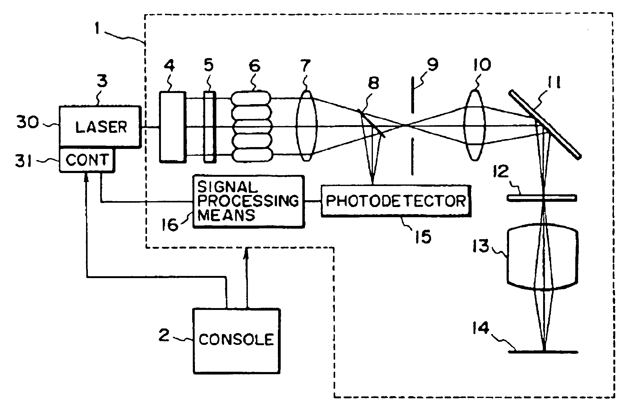
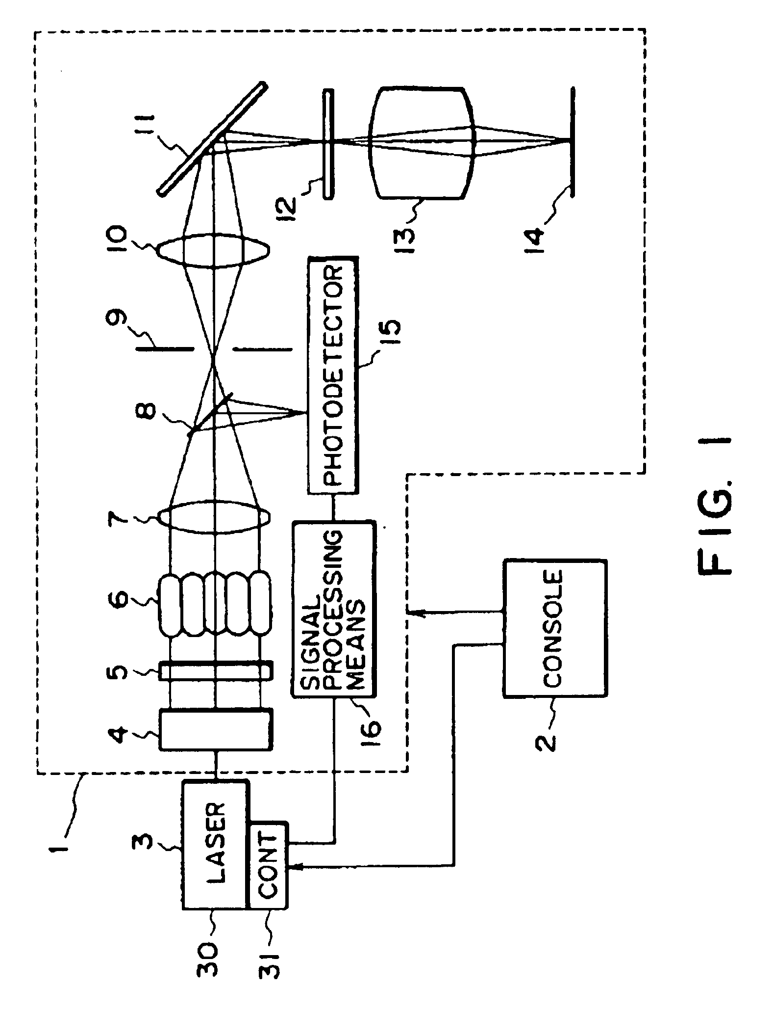
[0023]FIG. 1 shows an exposure apparatus according to an embodiment of the present invention. Denoted in FIG. 1 at 1 is a main assembly of a step-and-repeat or step-and-scan exposure apparatus, called a stepper. Denoted at 2 is a console with which an operator, for example, can apply a job command to a control system (not shown) in the exposure apparatus main assembly 1, for controlling the operation of the main assembly. Denoted at 3 is a laser light source having a gas laser device which is based on a noble gas halide excimer laser (called “excimer laser”), or an F2 laser, for example. Examples of such an excimer laser may be an XeCl excimer laser (308 nm wavelength), a KrF excimer laser (248 nm wavelength), and an ArF excimer laser (193 nm wavelength). The following description will be made of an example wherein the laser light source 3 uses a noble gas halide excimer laser.

[0024]The main assembly 1 of the exposure apparatus comprises a beam shaping optical system 4 for rectifyin...


PUM


Abstract

In a gas laser device, a laser gas sealingly stored in a chamber is excited using a discharging electrode that is electrically discharged. Laser light produced by the electrical discharging is totally reflected by a total reflection mirror. An output window partially reflects the laser light and outputs a portion of the laser light reflected between the total reflection mirror and the output window. A blower circulates the laser gas within the chamber so that the laser gas passing an electrical discharging region of the discharging electrode is circulated in the chamber and is returned to the electrical discharging region of the discharging electrode. The blower is operated according to the state of electrical discharging from the discharging electrode. The blower operation includes operating rotation of the blower in a stand-by state in which no laser gas is excited by the electrical discharging from said discharging electrode so that no laser light is emitted but the gas laser device is in a condition to output the laser light, and operating rotation of the blower in an in-operation state in which the laser gas is excited by the electrical discharging from said discharge electrode and laser light is outputted.

Description

FIELD OF THE INVENTION AND RELATED ART[0001]This invention relates to a gas laser device such as a noble gas halide excimer laser device or an F2 laser device, for example. In another aspect, the invention is concerned with an exposure apparatus or a semiconductor device manufacturing method wherein such a gas laser device is used as an exposure light source.[0002]In the field of semiconductor device production or other fields, a noble gas halide excimer laser (hereinafter, simply “excimer laser”), which is one of the types of gas lasers, has attracted much attention as a high power laser. As for such an excimer laser, there are an XeCl excimer laser (308 nm wavelength), a KrF excimer laser (248 nm wavelength), and an ArF excimer laser (193 nm wavelength), for example. Similarly, an F2 laser (158 nm wavelength) has attracted much attention as a high power laser. Also, semiconductor device manufacturing exposure apparatuses of the step-and-repeat type or step-and-scan type having a K...

Claims


Application Information

Patent Timeline
IPC IPC(8): H01S3/22H01S3/036
CPCH01S3/036H01S3/2251H01S3/2256H01S3/2258H01L21/027
Inventor SANO, NAOTONAGAI, YOSHIYUKI
Owner CANON KK
Why Eureka
Try Eureka