Expanded beam connector system

a beam connector and beam beam technology, applied in the field of beam beam connector systems, can solve problems such as unacceptable back reflection levels in telecom applications

Inactive Publication Date: 2006-04-18
TE CONNECTIVITY CORP
View PDF14 Cites 84 Cited by
  • Summary
  • Abstract
  • Description
  • Claims
  • Application Information

AI Technical Summary

Benefits of technology

[0003]The present invention avoids the aforementioned failure modes by reducing the power density of the signal transmission through beam expansion between the emitting and receiving fibers.
[0004]One aspect of the present invention is to provide an optical coupling system suitable for high power applications by expanding the beam. By expanding the beam, power density at the interface of the optical components is reduced. For example, by expanding the beam from a core size of about 10.4 microns to an expanded beam size of about 66 microns, the power density will be reduced by a factor of 40 (i.e., (66 / 10.4)2).

Problems solved by technology

In addition, the many interfaces with refractive index steps yield an unacceptable back reflection level for telecom applications.

Method used


Image

  • Expanded beam connector system
  • Expanded beam connector system
  • Expanded beam connector system

Examples


example 1

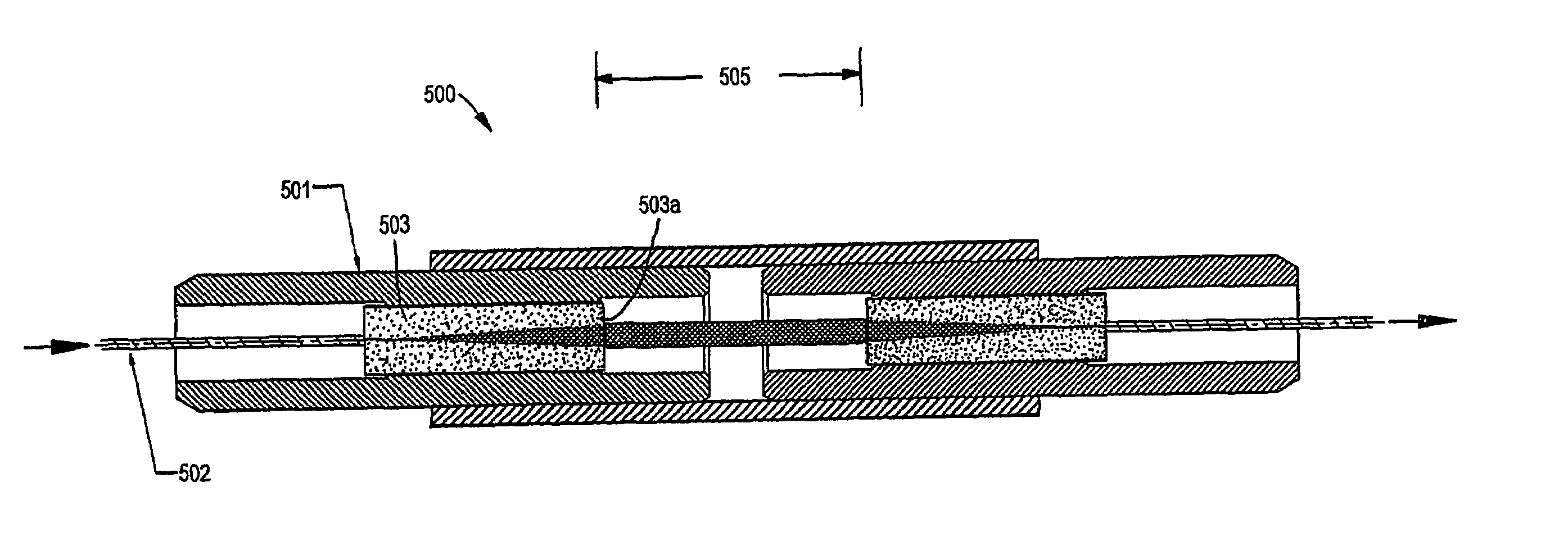
[0056]The method of manufacturing the connectors of the present invention can vary. The following is an example of a preferred manufacturing approach for either an FC or SC style connector having the expanded beam of the present invention. It should be understood that this example is for illustrative purposes only and should not be used in any way to limit the scope of the invention.[0057]Step 1. Receive lens / fiber pigtail from vendor[0058]SMF-28 fiber with 900 um buffer,[0059]length: 3 m[0060]from tip of lens to beginning of buffer: 11 / 10.5 mm[0061]lens length is ¼ pitch plus 17–22 μm for polishing[0062]Step 2. Assembly[0063]Connector sub-assembly parts:[0064]Ferrule: SM-126 / 127 μm bore (larger bore more readily accepts lens / fiber pigtail than SM-125 / 126 μm bore ferrule)[0065]Ferrule assembly: FC or SC[0066]Spring: standard[0067]Retainer body: standard[0068]Epoxy: 353 ND, SM cure schedule[0069]Alignment and cure fixture with “non-stick” physical stop[0070]Cure Requirement: lens tip...


PUM


Abstract

A method of coupling a high-power optical signal between an optical fiber and a mating optical component, the optical signal ranging in wavelength from x to y, and having a first diameter while propagating in a mode field within the fiber, the method comprising: (a) converting the high-power optical signal between the first diameter in the fiber and a second diameter significantly greater than the first diameter using a GRIN lens fused to an end of the fiber, the GRIN lens having a diameter substantially the same as that of the optical fiber and a length l complying with the following equation:¼x+½nx≦l≦¼y+½ny,wherein n=0, 1, 2, 3 . . . 100;(b) establishing physical contact between the GRIN lens and a coupling surface of the mating optical component; and (c) while the high-power optical signal is at the second diameter, optically coupling it between the lens and the mating optical component.

Description

REFERENCE TO RELATED APPLICATIONS[0001]This application claims priority to provisional application No. 60 / 307,684 filed Jul. 24, 2001 and provisional application No. 60 / 365,646 filed Mar. 19, 2002. Both of these applications are incorporated herein by reference including their appendices and any references which they incorporated by reference.BACKGROUND OF INVENTION[0002]There is a continuing need to reduce the number of optical amplifiers used in tele- and data-communication systems, and to increase the size of such systems. This need is best addressed by increasing the optical signal strength carried on the optical fibers. Conventional optical connectors, however, are limited in the signal strength that they can carry. Specifically, conventional connectors, especially those used in single mode applications, are incapable of supporting power transmissions at the level of about 1–3 watts. At these levels, surface anomalies and contamination at the interface of the fiber cores will c...

Claims


Application Information

Patent Timeline
Patent Type & Authority Patents(United States)
IPC IPC(8): G02B6/32G02B6/38G02B6/42
CPCG02B6/32G02B6/3851G02B6/3834G02B6/3813G02B6/3853
Inventor GRINDERSLEV, SORENMANNING, RANDY MARSHALLKEVERN, JAMES DAVID
Owner TE CONNECTIVITY CORP
Why Eureka
Try Eureka