[0019]In view of the above problems and limitations of existing distributed sensor networks and protocols and in accordance with the present invention, the importance of balancing the node
energy load, and reducing the data transmitted when the nodes are energy-constrained has been recognized. It would therefore be desirable to provide a network having a clustering-based protocol which utilizes randomized rotation of local cluster-heads, localized coordination to enable
scalability and robustness for dynamic networks, and the incorporation of data fusion into the
routing protocol to reduce the amount of information that must be transmitted to a base
station.
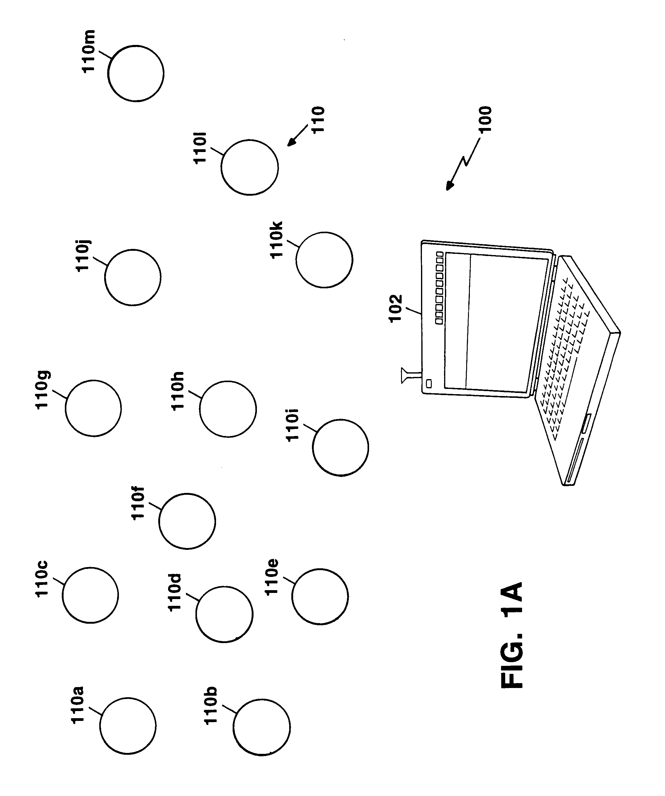
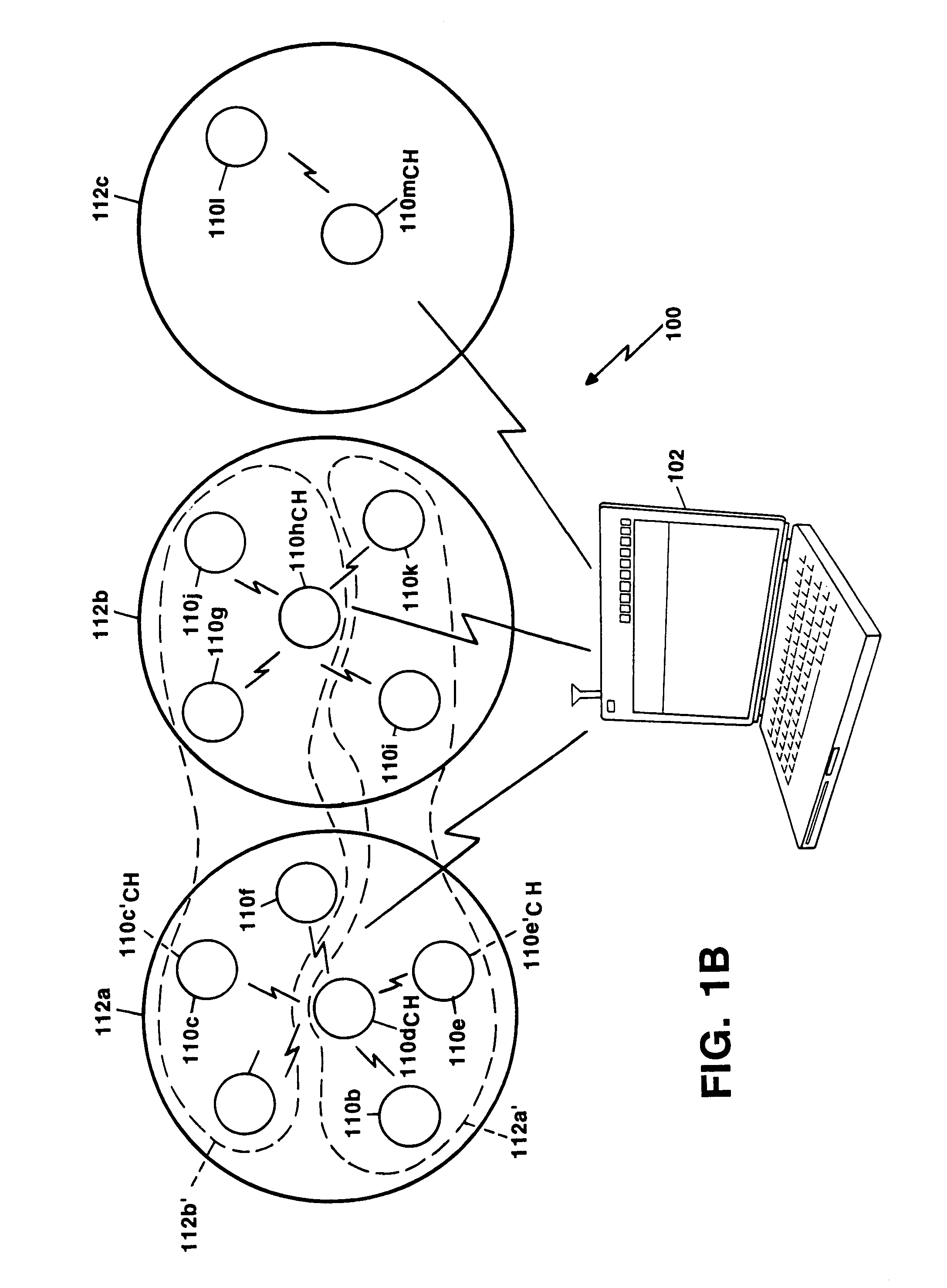
[0020]In accordance with an aspect of the present invention, a network includes a base
station and a plurality of nodes. Each of the nodes has a low energy mode, and a
high energy mode and are organized into node clusters. Each node cluster includes a designated cluster-head. Each of the nodes in the cluster collects information and transmits the information to the cluster-head. The cluster-head then transmits the information collected by the nodes in the cluster to the base station. The network further comprises means for selecting a new cluster-head and means for forming new clusters about the new cluster-heads. With such an arrangement, the network achieves energy-efficiency by (i) randomized, adaptive, self-configuring cluster formation, (ii) localized control for data transfers, and (iii) low-energy medium access. By providing for the selection of new cluster-heads, the
energy load is balanced in order to prolong the overall
system life. Moreover, all the nodes in the network can share the limited channel bandwidth by using local low energy transmissions separated spatially from one another in order to avoid interference. The nodes can also enter a
sleep mode to preserve energy. The nodes can additionally include attached microsensors or control interfaces.
[0021]In accordance with a further aspect of the present invention a method of forming a network from a plurality of nodes includes the steps of (a) forming the nodes into a plurality of clusters for a round of
data transmission, each of the plurality of clusters containing a cluster-head; (b) operating the cluster to transfer data; (c) selecting new cluster-heads; and (d) repeating steps (a)–(c) for a subsequent round of
data transmission. With such an implementation, an energy efficient protocol is provided. The cluster-heads schedule data transfers to minimize collisions and maximize
sleep time of the other nodes in the cluster, thereby reducing energy dissipation. Furthermore, the cluster formation is self configuring and fault tolerant.
[0022]In accordance with a still further aspect of the present invention a method of cluster operation includes the steps of collecting data in a cluster-head and reducing the
data transmission latency by using application-specific data aggregation to reduce the amount of redundant data transmitted from the cluster-head to a base station. Local data aggregation at the cluster-heads greatly reduces the amount of data that needs to be sent to the base station. An application-specific protocol architecture achieves the energy- and latency-efficiency needed for
wireless microsensor networks. In addition to helping avoid
information overload, data aggregation, also known as data fusion, can combine several unreliable correlated data measurements to produce a more accurate
signal by enhancing common signals and reducing uncorrelated
noise. Since the method is
application specific and can achieve a greater level of redundant
data reduction, the method is energy- and latency-efficient. Thus, application-specific data aggregation can also increase the
signal to
noise ratio of the data sent to the base station. The classification or higher level
processing of aggregated data can be performed manually (e.g., with the aid of a
human operator) or automatically. In one embodiment, the method of performing data aggregation and the classification
algorithm are application-specific. For example, acoustic signals are often combined using a
beamforming algorithm to reduce several signals into a single signal that contains the
relevant information of all the individual signals. Large energy gains can be achieved by performing the data fusion or classification
algorithm locally, thereby requiring much less data to be transmitted to the base station.
[0023]The benefits of the present techniques and
network topology include localized coordination and control for cluster setup and operation, randomized rotation of the cluster-heads and formation of the corresponding clusters, and local data aggregation to reduce global communication. The use of clusters for transmitting data to the base station leverages the advantages of short transmit distances for most nodes, requiring only a few nodes to transmit over far distances to the base station. The Low-Energy Adaptive Clustering Hierarchy (LEACH) technique of the present invention outperforms classical clustering algorithms by allowing the energy requirements of the network to be distributed among all the sensors. In addition, LEACH is able to perform local computation in each cluster to reduce the amount of data that must be transmitted to the base station. This achieves a large reduction in the energy dissipation, because computation is much less expensive than
RF communication.
[0024]In accordance with a still further aspect of the present invention, it is possible to form the clusters by collecting data on the status of each of the plurality of nodes and assigning each of the plurality of nodes to a particular cluster. With such an alternative cluster formation method, the base station can form clusters, which will generally be more efficient than those formed using a
distributed algorithm as described above. However, the improved cluster formation is at the expense of requiring that each node transmit information to the base station at the beginning of each round about its location.

