
Lordotic fusion implant

a fusion implant and vertebral technology, applied in the field of intervertebral fusion implants, can solve the problems of disc herniation or protrusion, disc breakage or degeneration, and variety of problems or disease states, and achieve the effects of maximizing preservation of posterior bony and ligament spinal elements, reducing the retraction of neural structures, and simple manufacturing

Inactive Publication Date: 2006-05-16
ZIMMER SPINE INC
View PDF11 Cites 117 Cited by
  • Summary
  • Abstract
  • Description
  • Claims
  • Application Information

AI Technical Summary

Benefits of technology

[0010]It is the object of this invention to provide an expandable intervertebral fusion implant that is both simple to manufacture and simple to use in daily clinical surgical practice while remaining versatile enough to address the complex biologic and pathologic variability of the human spine.
[0012]To achieve these objectives, a pair of metal shells are distracted inside an intervertebral space that has been appropriately prepared for fusion. An expansible installation tool is used to achieve optimal distraction, and the shells are held apart by teeth on legs which extend from semicylindrical bases. These legs preferably are curved to facilitate differential expansion of one end of the implant relative to the other to account for normal variations in the angle of the adjacent end plates; i.e., to preserve or enhance the lordotic or kyphotic attitude of adjacent vertebral body elements that are to be fused. The installation tool is then unscrewed and disengaged, leaving the component parts as a stable assembly that can be packed with bone to promote osseous union.
[0016]The advantages provided by this invention include (1) the fact that both the tool and the implant components are of simple manufacture and (2) because of its expandable nature, this implant has the potential for use in microsurgical laminotomy, where only a small opening is made in the spine, resulting in minimal retraction of neural structures and maximizing preservation of posterior bony and ligaments spinal elements, and (3) lordotic and kyphotic orientations in the spine can be addressed. Most existing posterior interbody approaches require extensive bone removal to achieve spinal fusion whether or not an implant is used.

Problems solved by technology

As a result, the stresses acting upon the human backbone (or “vertebral column”), are unique in many senses, and result in a variety of problems or disease states that are peculiar to the human species.
The repetitive forces which act on these intervertebral discs during repetitive day-to-day activities of bending, lifting and twisting cause them to break down or degenerate over time.
Disruption of a disc's internal architecture leads to bulging, herniation or protrusion of pieces of the disc and eventual disc space collapse.
In addition, loss of disc space height relaxes tension on the longitudinal spinal ligaments, thereby contributing to varying degrees of spinal instability such as spinal curvature.
While cancellous bone appears ideal to provide the biologic components necessary for osseous union to occur, it does not initially have the strength to resist the tremendous forces that may occur in the intervertebral disc space, nor does it have the capacity to adequately stabilize the spine until long term bony union occurs.
For these reasons, may spinal surgeons have found that interbody fusion using bone alone has an unacceptably high rate of bone graft migration or even expulsion or nonunion due to structural failure of the bone or residual degrees of motion that retard or prohibit bony union.
The degree of expansion is rather limited, however.
The prior devices do not enable one to achieve great ranges of implant height, or to adjust taper angle for kyphotic and lordotic situations.
During implantation from an anterior approach (from the front of the body), excessive retraction (pulling) is often required on the great blood vessels which greatly enhances the risk of devastating complications such as vascular tears or thrombosis.
On the other hand, during a posterior approach, large implant diameters may require excessive traction on neural elements for adequate placement, even if all posterior bony elements are removed.
In some instances, an adequate implant size cannot be inserted posteriorly, particularly if there is a significant degree of ligamentous laxity requiring higher degrees of distraction to obtain stability by tautening the annular ligamentous tension band.
Compromising on implant size risks sub-optimal stability or a loose implant, which has a greater chance for migration within or expulsion from the disc space.
The alternative of excessively retracting neural elements to facilitate a posterior implant application results in a neuropraxia at best and permanent neural damage at worst.

Method used


Image

  • Lordotic fusion implant
  • Lordotic fusion implant
  • Lordotic fusion implant

Examples


Embodiment Construction

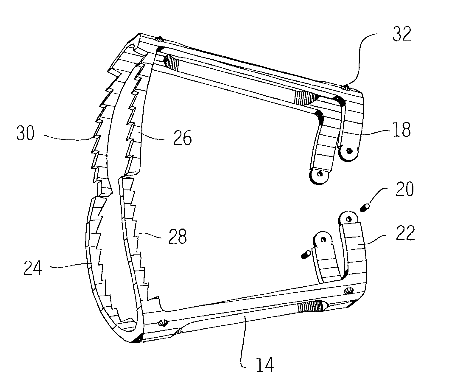
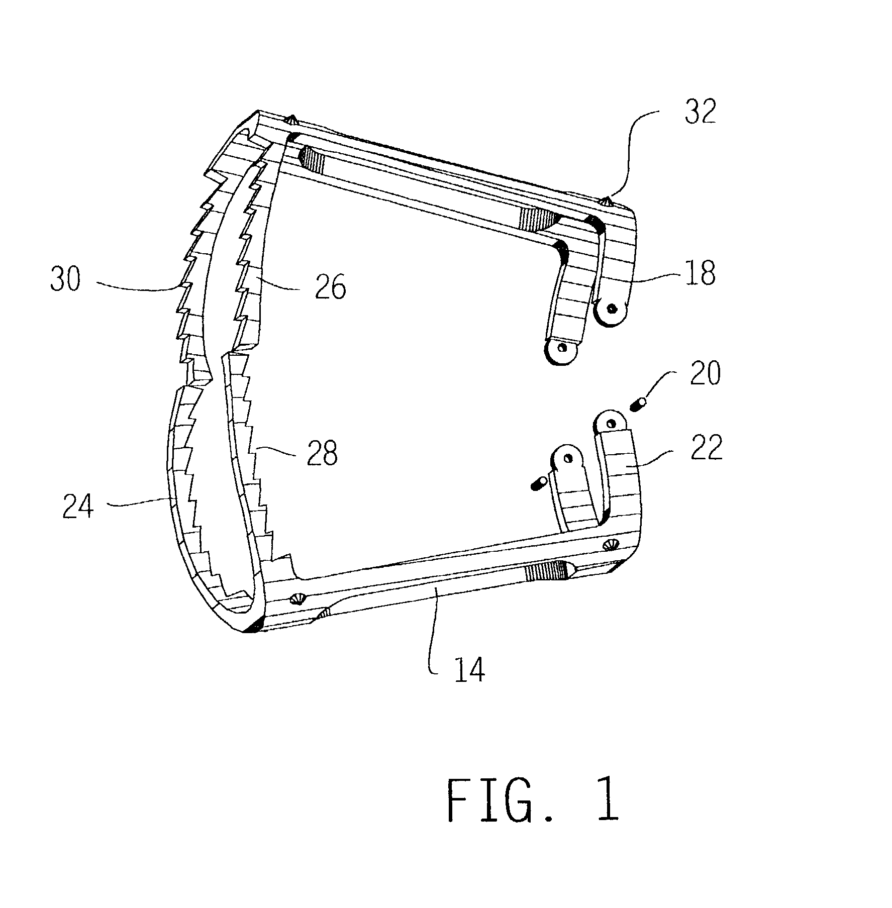
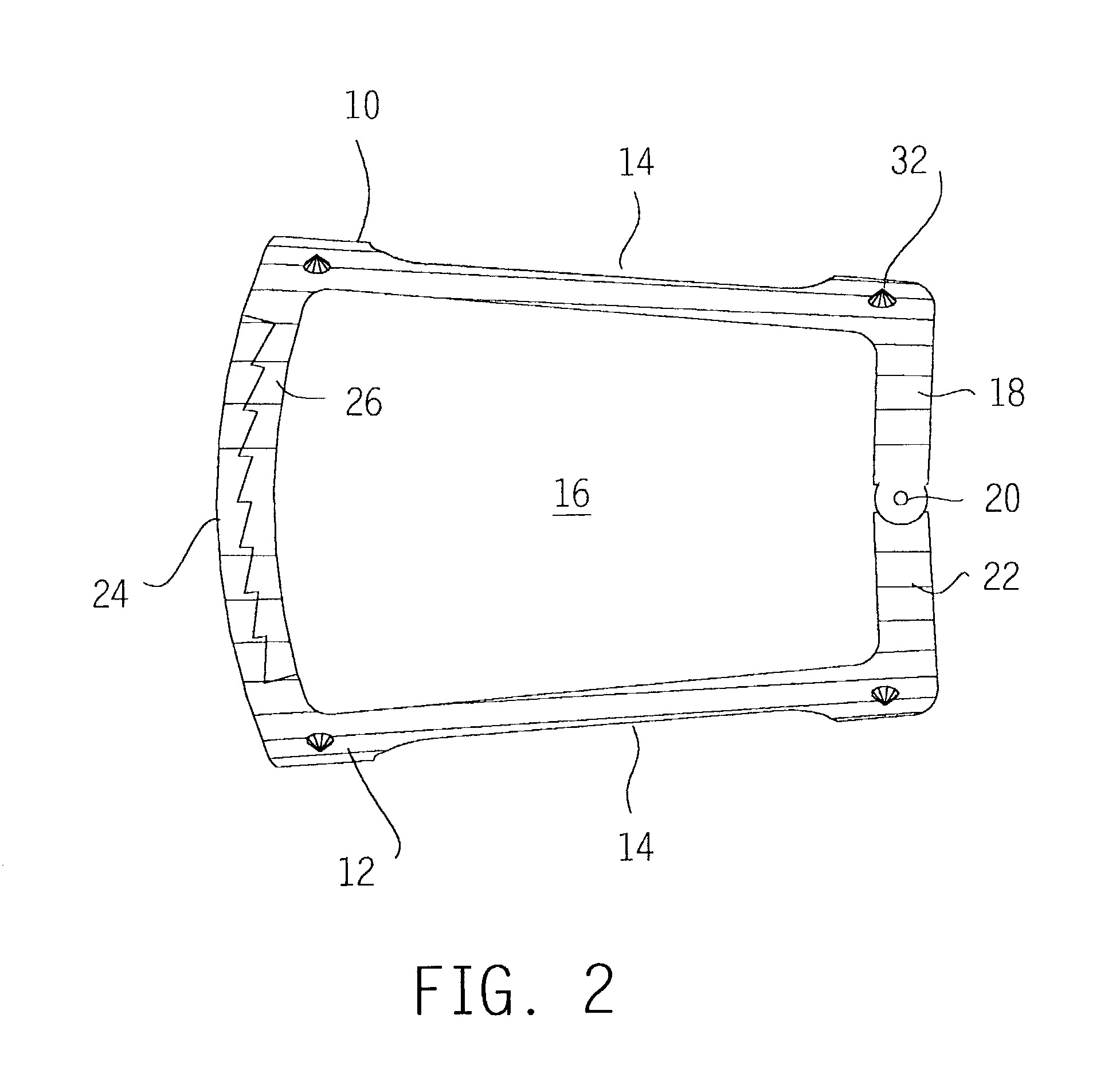
[0021]An expandable intervertebral fusion implant embodying the invention appears in FIGS. 1–3. The implant comprises a pair of mating metal shells 10, 12. Each shell is generally sermicylindrical or, more accurately, semi-frustoconical. The vertical and horizontal bone growth windows 14, 16 define four legs on each shell: the two shorter legs 18 on the upper shell 10 are connected by hinge pins 20 to the opposite legs 22 on the lower shell 12. The longer legs 24 on the lower shell overlap those 26 on the upper shell, and these legs have teeth 28, 30 on their overlapping surfaces. The teeth are raked in opposite directions, to permit expansion of the shells by a surgeon, but to prevent unintended collapse thereafter. The ratcheting action also provides useful tactile or audible feedback to the surgeon. In one embodiment of the invention, each of the teeth 28, 30 on each of their respective legs 24, 26 are equidistant (for example, distances R in FIG. 3) from the hinge pins 20.

[0022]...


PUM

PropertyMeasurementUnit
diameteraaaaaaaaaa
heightaaaaaaaaaa
sizeaaaaaaaaaa

Abstract

An expandable intervertebral fusion implant includes a pair of shells having mating surfaces which resist shifting when the parts are assembled. The shells have opposed legs provided with teeth which permit the shells to be ratcheted outward in a non-parallel fashion after they have been placed between spinal elements.

Description

BACKGROUND OF THE INVENTION[0001]This invention relates to an intervertebral fusion implant. The class of implements to which this invention pertains serve to stabilize adjacent vertebral elements, thereby facilitating the development of a bony union between them and thus long term spinal stability.[0002]Of all animals possessing a backbone, human beings are the only creatures who remain upright for significant periods of time. From an evolutionary standpoint, this erect posture has conferred a number of strategic benefits, not the least of which is freeing the upper limbs for purposes other than locomotion. From an anthropologic standpoint, it is also evident that this unique evolutionary adaptation is a relatively recent change, and as such has not benefitted from natural selection as much as have backbones held in a horizontal attitude. As a result, the stresses acting upon the human backbone (or “vertebral column”), are unique in many senses, and result in a variety of problems ...

Claims


Application Information

Patent Timeline
Patent Type & Authority Patents(United States)
IPC IPC(8): A61F2/44A61F2/00A61F2/02A61F2/28A61F2/30
CPCA61F2/28A61F2/44A61F2/4455A61F2310/0097A61F2/30965A61F2002/2817A61F2002/2835A61F2002/2839A61F2002/30113A61F2002/30115A61F2002/30125A61F2002/30133A61F2002/30156A61F2002/30354A61F2002/30492A61F2002/30522A61F2002/30538A61F2002/30599A61F2002/30604A61F2002/30624A61F2002/30677A61F2002/30777A61F2002/30785A61F2002/30841A61F2002/4475A61F2220/0025A61F2220/0033A61F2230/0006A61F2230/0008A61F2230/0015A61F2230/0023A61F2250/0006A61F2250/0063A61F2310/00011A61F2310/00017A61F2310/00023A61F2310/00173A61F2310/00179A61F2310/00796A61F2/30767A61F2002/30593
Inventor SUDDABY, LOUBERT
Owner ZIMMER SPINE INC
Learn More