MMIC transceiver and low cost subharmonically driven microwave receiver

a subharmonically driven, microwave receiver technology, applied in the field of communication, can solve the problems of not being able to drive down not being able to achieve the effect of reducing the cost of vsats, and not being able to have a large number of smaller devices

Inactive Publication Date: 2006-05-16
REVEAL IMAGING
View PDF13 Cites 21 Cited by
  • Summary
  • Abstract
  • Description
  • Claims
  • Application Information

AI Technical Summary

Benefits of technology

[0016]In yet another aspect of the present invention, a local oscillator circuit generates the local oscillator signal that passes through a low pass filter into the mixer. A bandpass filter receives the RF signal and passes the signal after bandpass through the mixer circuit. The mixer can further comprise a field effect t

Problems solved by technology

It was not convenient to have a large number of smaller, earth station terminals.
In many current VSAT designs, the MMW transceiver circuit accounts for almost 75% of the total cost of a VSAT terminal.
Although this method is widely used, it has not been very successful at driving down the costs of VSATs because the packaging of MMIC's and the required tuning after assembly has been expensive

Method used


Image

  • MMIC transceiver and low cost subharmonically driven microwave receiver
  • MMIC transceiver and low cost subharmonically driven microwave receiver
  • MMIC transceiver and low cost subharmonically driven microwave receiver

Examples


Embodiment Construction

[0036]The present invention will now be described more fully hereinafter with reference to the accompanying drawings, in which preferred embodiments of the invention are shown. This invention may, however, be embodied in many different forms and should not be construed as limited to the embodiments set forth herein. Rather, these embodiments are provided so that this disclosure will be thorough and complete, and will fully convey the scope of the invention to those skilled in the art. Like numbers refer to like elements throughout.

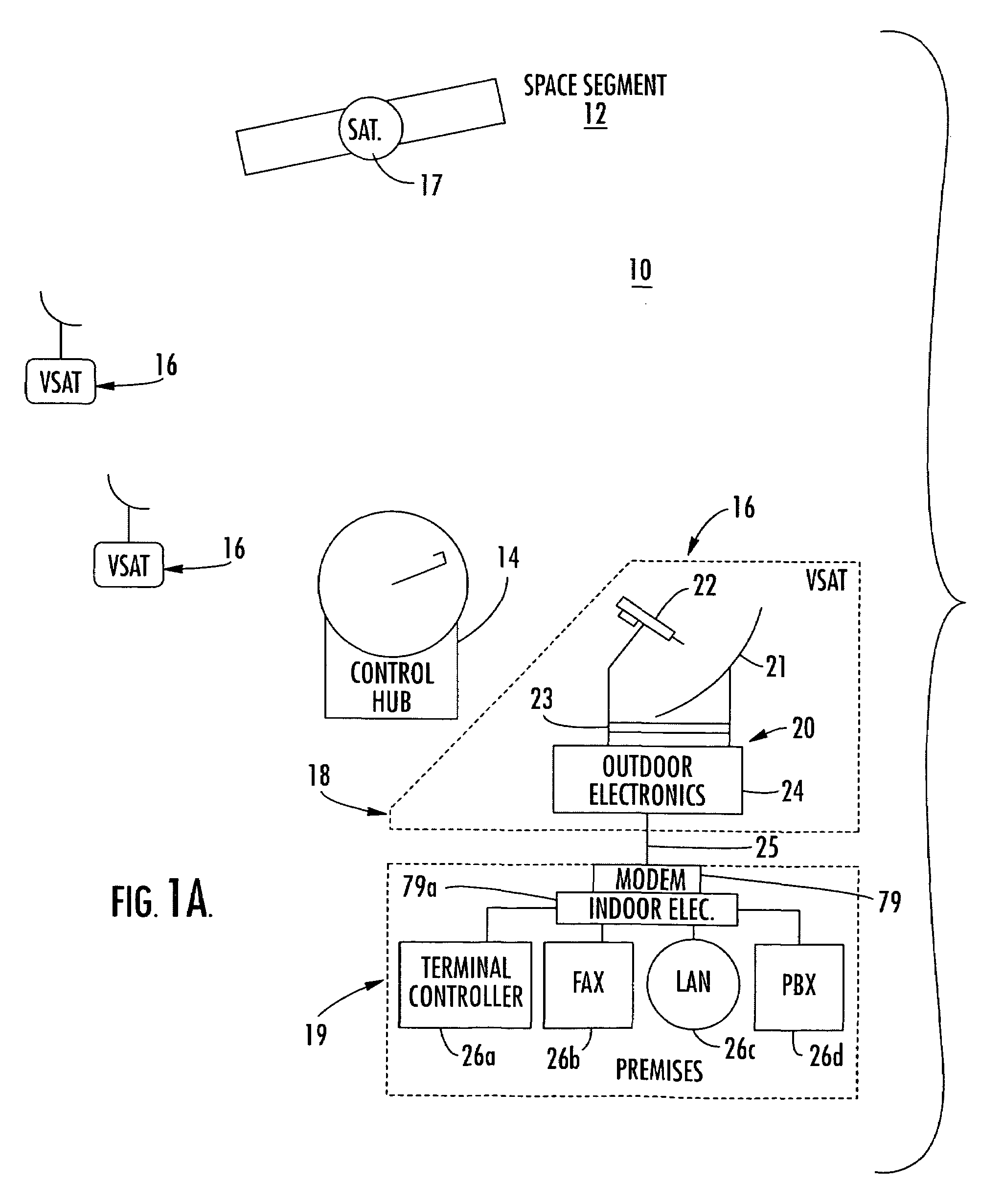
[0037]FIG. 1A illustrates a block diagram of a very small aperture terminal (VSAT) network or communications system 10 showing basic elements of the space segment 12, a control hub also referred to as a master earth station 14, and a number of VSAT remote earth stations 16 also referred to individually as VSATs or VSAT terminals. The space segment 12 includes a number of satellites 17 (only one shown but typically at least three) used for satellite communi...


PUM


Abstract

A receiver is operable at microwave frequencies and includes a substrate and waveguide-to-microstrip transition formed on the substrate for receiving microwave radio frequency (RF) signals. Surface mounted receiver components are interconnected with microstrip formed on the substrate and receive the RF signals from the waveguide-to-microstrip transition and convert the signal to an intermediate frequency (IF) for further processing. The surface mounted receiver components include a mixer circuit that receives a local oscillator (LO) signal and RF signal to produce the IF signal. A diplexer circuit and a temperature compensated attenuator circuit received the IF signal from the mixer and attenuates the IF signal to provide high signal linearity and high order modulation.

Description

RELATED APPLICATION[0001]This application is a continuation-in-part application of patent application Ser. No. 10 / 301,511, filed Nov. 21, 2002, and entitled “LOW COST VSAT MMIC TRANSCEIVER WITH AUTOMATIC POWER CONTROL,” which is based upon prior filed provisional application Ser. No. 60 / 408,513, filed Sep. 5, 2002, the disclosures which are hereby incorporated by reference in their entirety.FIELD OF THE INVENTION[0002]This invention relates to the field of communications, and more particularly, this invention relates to the field of microwave receivers.BACKGROUND OF THE INVENTION[0003]In the early days of satellite communications, there were few downlink earth stations and those in existence were essentially large antenna dishes operative with wired communications hubs. Any signals received at these large earth stations were distributed through wires and cables to numerous destinations and even other communications hubs. Thus, many earth stations were positioned in metropolitan area...

Claims


Application Information

Patent Timeline
IPC IPC(8): H04B7/185H04H20/00
CPCH04B7/18528H04B7/18517H04B7/185H05K1/18
Inventor AMMAR, DANNY F.STAHLY, STEPHEN A.
Owner REVEAL IMAGING
Why Eureka
Try Eureka