Band type multicontact electrode and method of making the same

Inactive Publication Date: 2006-05-16
BOSTON SCI NEUROMODULATION CORP
View PDF26 Cites 90 Cited by
  • Summary
  • Abstract
  • Description
  • Claims
  • Application Information

AI Technical Summary

Benefits of technology

[0014]The construction method of the present invention is more simplified than others known in the art, and hence provides a more reliabl

Problems solved by technology

Disadvantageously, making such electrodes or connectors becomes extremely difficult, especially when the contacts are very small and/or a large number of contacts are required.
One of the main problems encountered in the fabrication of such electrodes or connectors is to find a reliable method of holding the system of contacts in th

Method used


Image

  • Band type multicontact electrode and method of making the same
  • Band type multicontact electrode and method of making the same
  • Band type multicontact electrode and method of making the same

Examples


Embodiment Construction

[0033]The following description is of the best mode presently contemplated for carrying out the invention. This description is not to be taken in a limiting sense, but is made merely for the purpose of describing the general principles of the invention. The scope of the invention should be determined with reference to the claims.

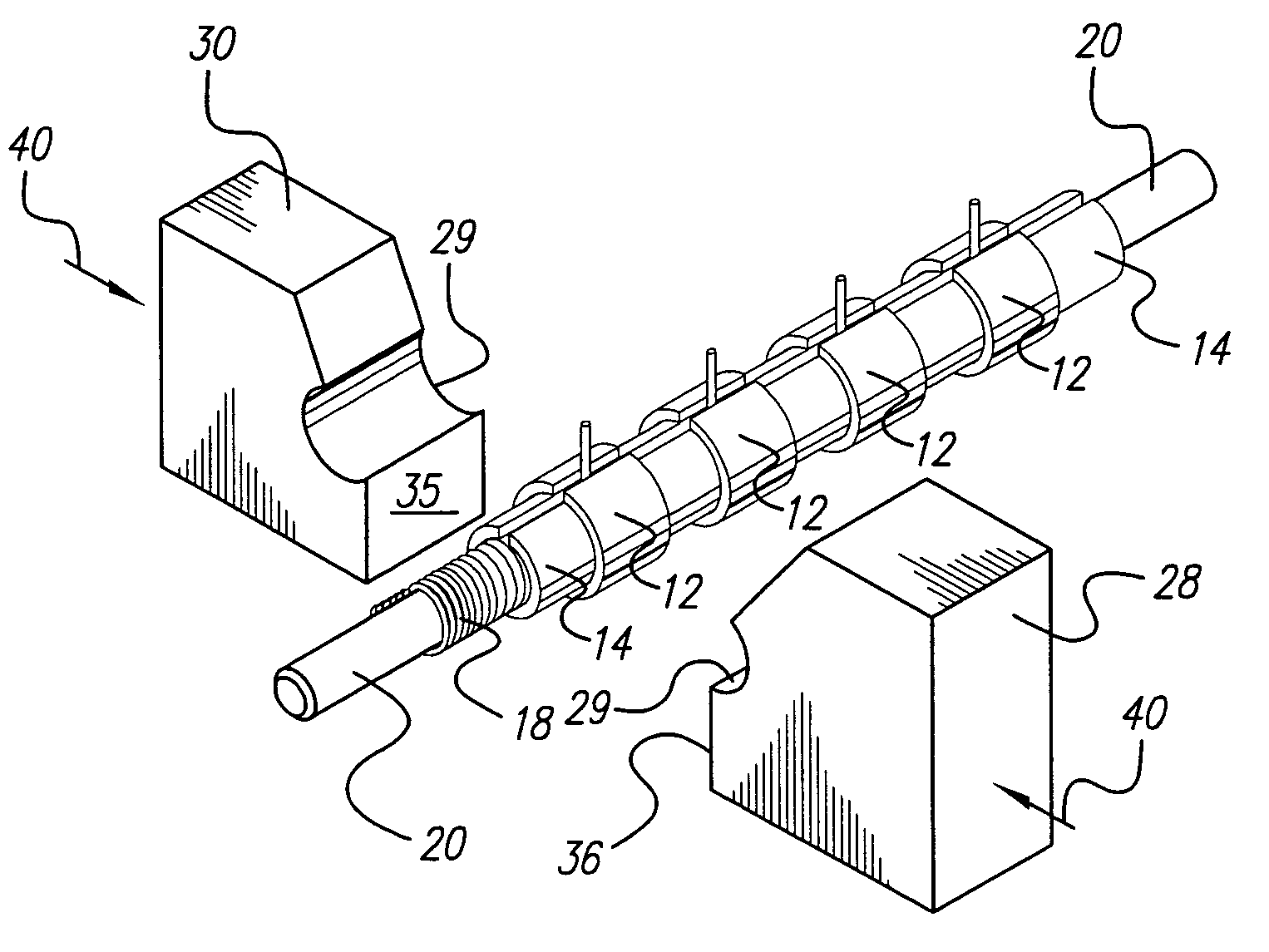
[0034]The invention described herein teaches a manufacturing technique for an implantable electrode array having multiple ring (or band) contacts. Typically, each ring or band contact is evenly spaced along the longitudinal axis of the lead, although unevenly spaced contacts could also be made.

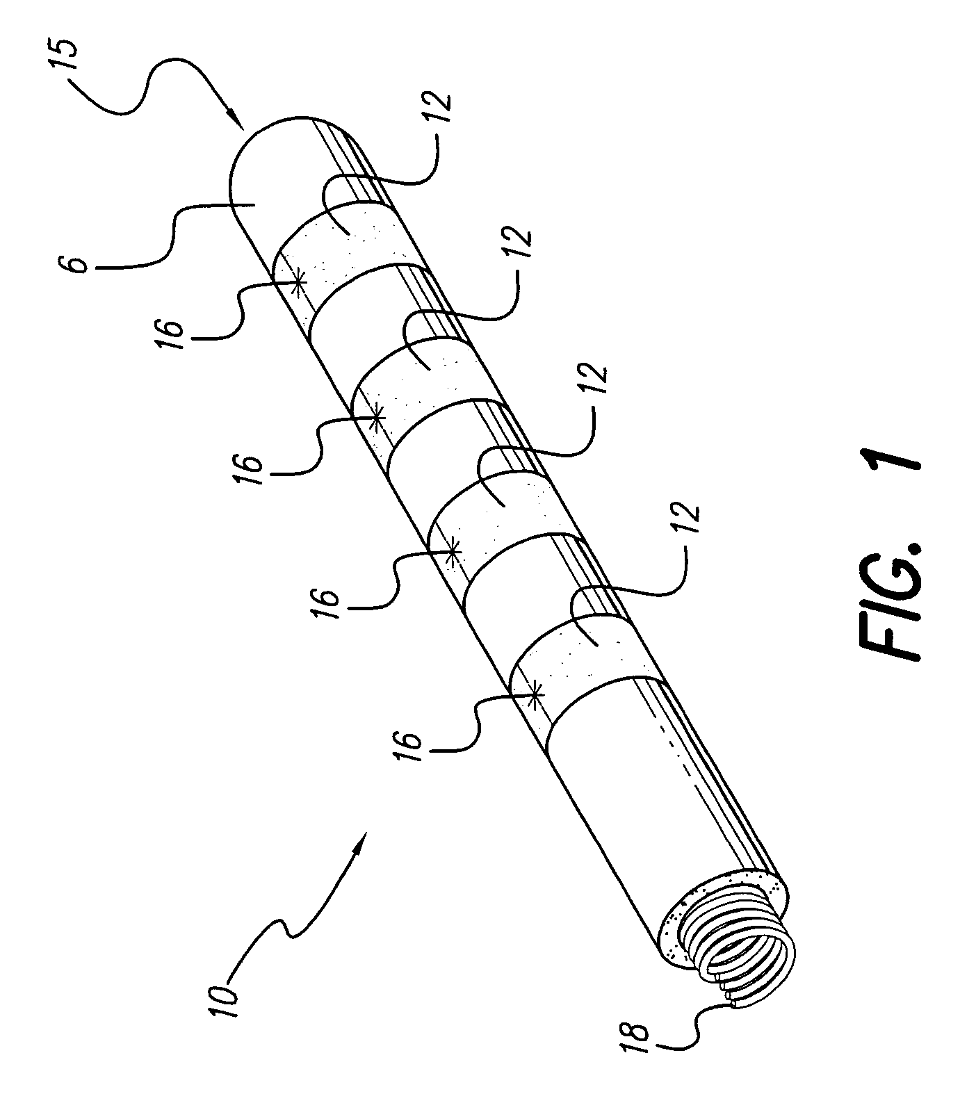
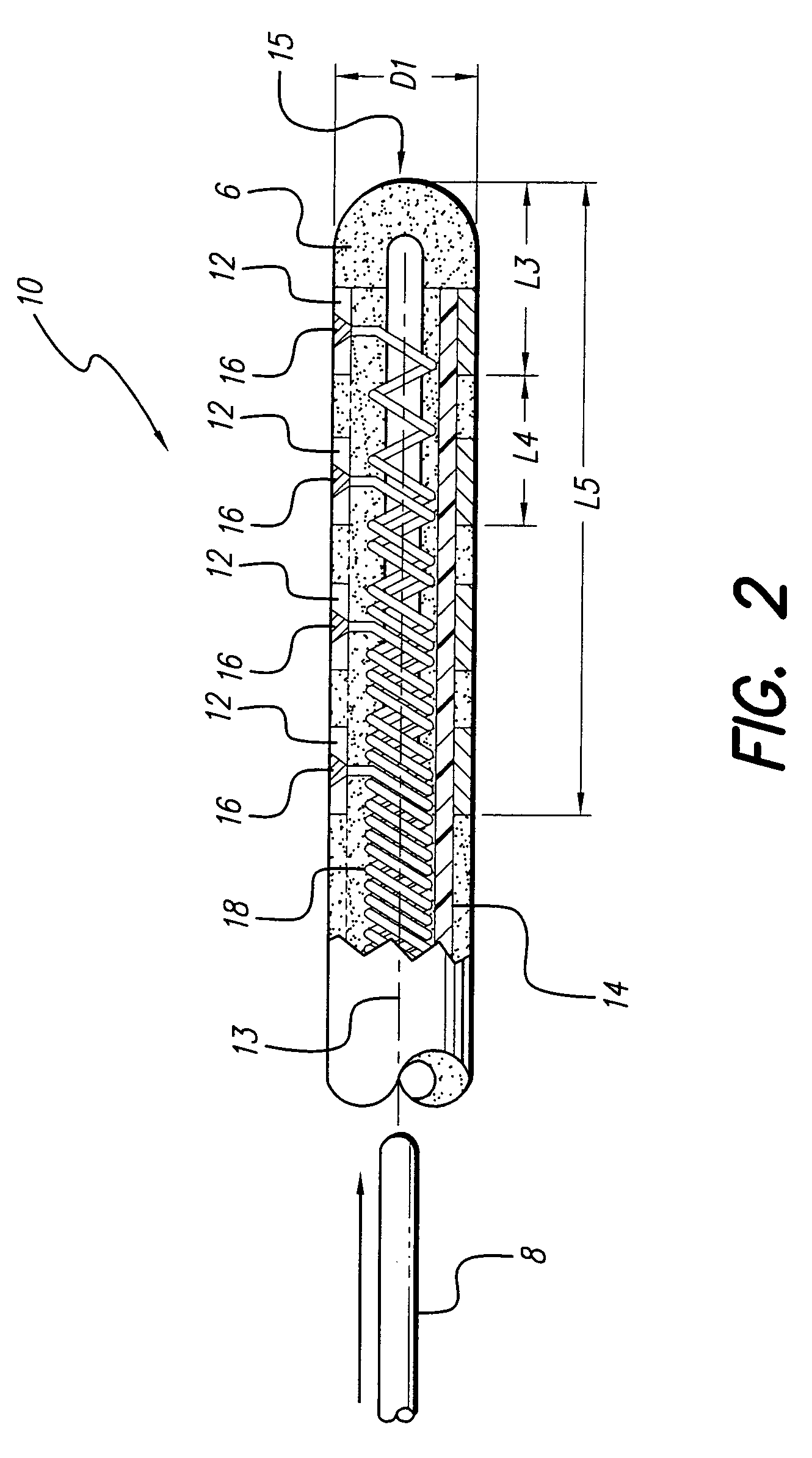
[0035]FIG. 1 shows a preferred embodiment of an electrode array 10 with four ring contacts 12 made in accordance with the invention. The number of contacts can vary depending on the purpose for which the electrode array is to be used. The electrode array of the present invention may be used with any suitable implantable pulse generator, and may have as few as one conta...


PUM

PropertyMeasurementUnit
Lengthaaaaaaaaaa
Forceaaaaaaaaaa
Flexibilityaaaaaaaaaa

Abstract

A multicontact electrode array suitable for implantation in living tissue includes a distal end having multiple spaced-apart ring or band electrode contacts carried on a flexible tube carrier. Each ring electrode contact is laser welded to a respective wire tip that has a multi-helix orientation on the inside of a separation tube. The center of the multi-helix wire defines a lumen wherein a positioning stylet, or other suitable positioning tool, may be removably inserted when the electrode array is implanted. The method of making the multicontact electrode array includes, as an initial step, winding lead wires around a suitable mandrel so as to form a multi-helix configuration. (Alternatively, the wire may be purchased in a multiwire pre-wound configuration that defines a lumen, in which case the mandrel is slipped inside the lumen.) Then, at a distal end of the electrode, each wire within the multi-helix winding is unwound so as to protrude out from the winding. Next, a non-conductive separation silicone tube which has a longitudinal slit along its length, is placed around the wound wires. Ring contacts are then placed over the silicone tube at a distal end of the electrode array and spaced apart as desired. These ring contacts also have a slit therein through which the protruding wire ends may exit. The silicone tube is used as a spacer to centrally locate the multi-helix wound wires with the ring contacts. A compressive die may be used to hold the pre-assembled ring contact, multi-helix wire, separation tube in their desired positions, and may be used to close the opening or slit of each ring contact through which the wire tips protrude. The wire tips are then individually trimmed to a suitable distance. A laser welding process may then be used to bond each lead wire to a corresponding ring contact. Finally, the preassembled electrode array is placed in a molding die, and a polymer filler is injected into the internal gaps of the electrode array components.

Description

[0001]The present application is a Divisional of U.S. application Ser. No. 09 / 970,406, filed Oct. 02, 2001 now abandoned; which claims the benefit of U.S. Provisional Application Ser. No. 60 / 239,154, filed Oct. 10, 2000, which applications are incorporated herein by reference.BACKGROUND OF THE INVENTION[0002]The present invention relates to the field of implantable electrodes, and more particularly to a multicontact band type electrode array. In a preferred embodiment, such multicontact band type electrode array is used with an implantable stimulator to provide electrical stimulation to body tissue, for example, to brain tissue for brain stimulation, to selected nerves for neural stimulation, or to the spinal cord for spinal cord stimulation (usually done to control or manage pain). Additionally, the present invention further provides a simple and reliable method of constructing a multicontact band type electrode array.[0003]Spinal cord and other stimulation systems are known in the...

Claims


Application Information

Patent Timeline
IPC IPC(8): A61N1/04A61N1/05
CPCA61N1/0529B29C33/126A61N1/0551B29L2031/753
Inventor KUZMA, JANUSZ A
Owner BOSTON SCI NEUROMODULATION CORP
Why Eureka
Try Eureka