Metal film vapor phase deposition method and vapor phase deposition apparatus

Inactive Publication Date: 2006-05-23
CANON ANELVA CORP
View PDF19 Cites 38 Cited by
  • Summary
  • Abstract
  • Description
  • Claims
  • Application Information

AI Technical Summary

Benefits of technology

[0011]It is an object of the present invention to provide a copper film vapor phase deposition method capable of forming, with high reproducibility, a copper film containing no residu

Problems solved by technology

(1) Since material compounds are very expensive, the cost of the copper film formed increases.
(2) Sublimation is very difficult to control, and this makes it difficult to form thin unif

Method used


Image

  • Metal film vapor phase deposition method and vapor phase deposition apparatus
  • Metal film vapor phase deposition method and vapor phase deposition apparatus

Examples


first embodiment

(First Embodiment)

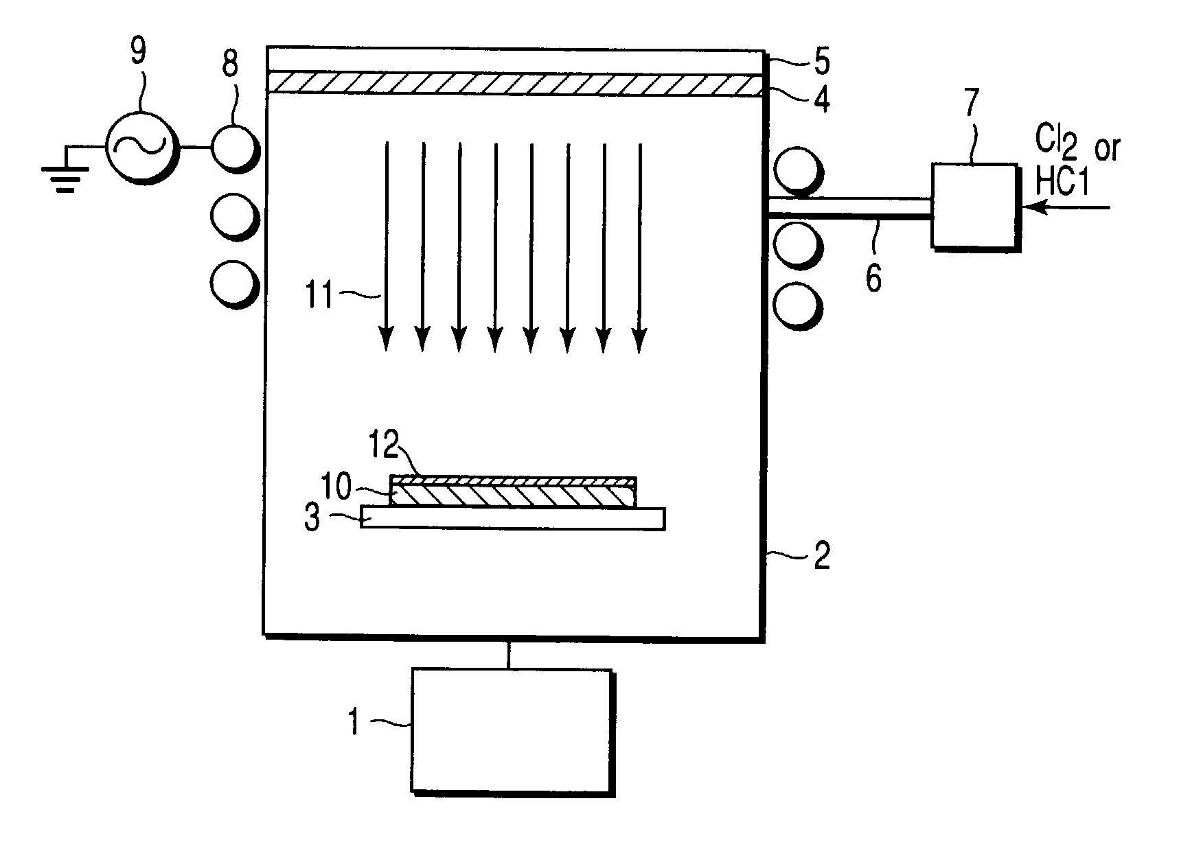
[0043]FIG. 1 is a schematic view showing a copper film vapor phase deposition apparatus according to the first embodiment.

[0044]In a box-shaped reactor vessel 2 having a bottom portion to which an exhaust member 1 such as a vacuum pump is connected, a second temperature control means e.g., a plate-like heating member 3 on which a substrate to be processed is placed is set. High-purity copper, e.g., high-purity copper plate 4 is set in the upper portion of the reactor vessel 2 so as to oppose the heating member 3. High-purity copper herein mentioned means that the purity of copper is 99.9% or more.

[0045]Note that the shape of this high-purity copper need not be a plate but can be, e.g., a block.

[0046]A first temperature control means, e.g., a heating / cooling member 5 is placed on the surface of the high-purity copper plate 4 away from the surface opposite to the heating member 3.

[0047]A gas supply pipe 6 for supplying a gas containing chlorine gas (or a gas containi...

second embodiment

(Second Embodiment)

[0062]A copper film formation method according to the second embodiment will be explained below by using the copper film vapor phase deposition apparatus shown in FIG. 1 described above.

[0063]First, a substrate 10 to be processed is placed on a heating member 3 in a reactor vessel 2. An exhaust member 1 is operated to exhaust a gas (air) in the reactor vessel 2 to set a predetermined vacuum degree.

[0064]Subsequently, a gas containing hydrogen chloride (HCl) is supplied into the reactor vessel 2 through a gas supply pipe 6. The flow rate of this hydrogen chloride-containing gas is controlled by a flow rate controller 7 inserted into the gas supply pipe 6. The temperature of high-purity copper (e.g., high-purity copper plate) 4 placed in the upper portion of the reactor vessel 2 is controlled by a heating / cooling member 5. After the temperature of this high-purity copper plate 4 is thus controlled, an RF power supply 9 applies an RF power of 13.56 MHz to an RF coil ...

third embodiment

(Third Embodiment)

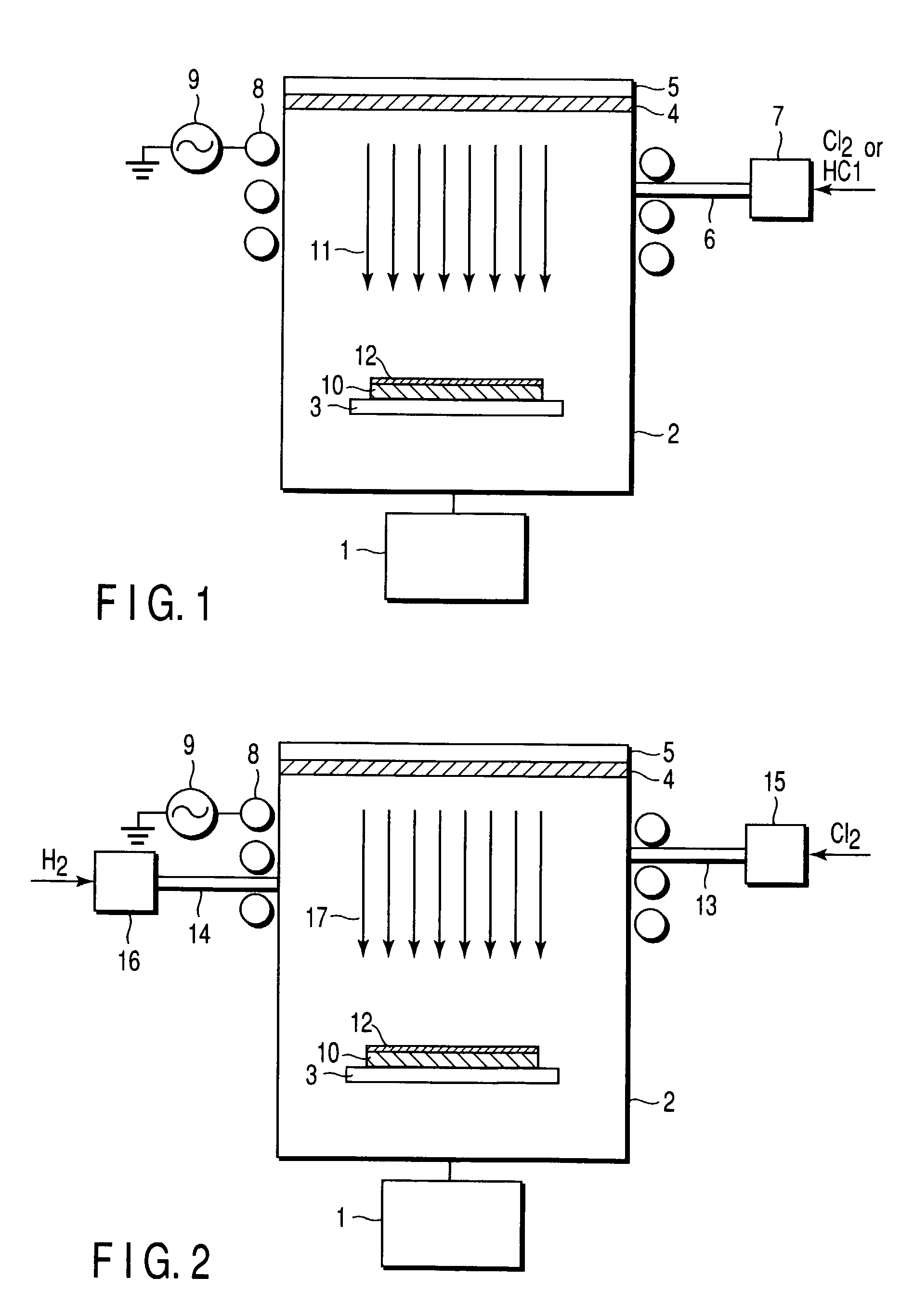
[0074]FIG. 2 is a schematic view showing a copper film vapor phase deposition apparatus according to the third embodiment. The same reference numerals as in FIG. 1 denote the same parts in FIG. 2, and a detailed description thereof will be omitted.

[0075]This vapor phase deposition apparatus includes a first gas supply pipe 13 connected to an upper side wall of a reactor vessel 2 to supply a gas containing chlorine, and a second gas supply pipe 14 connected to that upper side wall of the reactor vessel 2, which is opposite to the first gas supply pipe 13, to supply hydrogen. Flow rate controllers 15 and 16 are inserted into these first and second gas supply pipes 13 and 14, respectively.

[0076]Referring to FIG. 2, high-purity copper (e.g., high-purity copper plate) 4 is set in the upper portion of the reactor vessel 2, and a heating member 3 on which a substrate 10 to be processed is placed and an exhaust member 1 are set in the lower portion of the reactor vessel 2....


PUM

PropertyMeasurementUnit
Temperatureaaaaaaaaaa
Purityaaaaaaaaaa

Abstract

A copper film vapor phase deposition method includes the steps of exposing high-purity copper to a plasma of a gas containing chlorine gas to etch the high-purity copper, thereby generating active CuxCly, wherein x is 1 to 3, y is 1 to 3, gas, and forming a copper film by transporting the CuxCly gas onto the surface of a substrate to be processed. By using inexpensive high-purity copper and inexpensive chlorine, hydrogen chloride, or chlorine and hydrogen as source gases, a copper film containing no residual impurity such as carbon and having high film quality can be formed with high reproducibility.

Description

CROSS-REFERENCE TO RELATED APPLICATIONS[0001]This application is based upon and claims the benefit of priority from the prior Japanese Patent Applications No. 2001-241168, filed Aug. 8, 2001; and No. 2002-025975, filed Feb. 1, 2002, the entire contents of both of which are incorporated herein by reference.BACKGROUND OF THE INVENTION[0002]1. Field of the Invention[0003]The present invention relates to a copper film vapor phase deposition method and vapor phase deposition apparatus applied to, e.g., the formation of a wiring material film of a semiconductor device.[0004]2. Description of the Related Art[0005]For example, a thin copper (Cu) film used as a wiring material and the like is formed by physical film formation methods such as vacuum deposition, ion plating, and sputtering, and by chemical vapor deposition (CVD). In particular, CVD is generally extensively used because the method has superior surface covering properties.[0006]A conventionally known copper film formation method...

Claims


Application Information

Patent Timeline
IPC IPC(8): C23C16/14C23C16/448C23C16/50C23C16/08C23C14/22H01L21/285
CPCC23C16/14C23C16/4488C23C16/448C23C14/22
Inventor SAKAMOTO, HITOSHIYAHATA, NAOKI
Owner CANON ANELVA CORP
Why Eureka
Try Eureka