Multilayer capacitor

a multi-layer capacitor and capacitor technology, applied in the field of multi-layer capacitors, can solve the problems of difficult voltage fluctuation control, higher-speed and larger current fluctuation, and difficult to control voltage fluctuation, so as to enhance the operation and effect of multi-layer capacitors of the respective modes

Active Publication Date: 2006-05-23
TDK CORPARATION
View PDF7 Cites 18 Cited by
  • Summary
  • Abstract
  • Description
  • Claims
  • Application Information

AI Technical Summary

Benefits of technology

[0016]Consequently, in the multilayer capacitor according to this mode, magnetic fluxes generated by high-frequency current passing in the internal conductors are cancelled by each other to reduce parasitic inductance that the multilayer capacitor itself has, so that equivalent series inductance (ESL) is reduced. Accordingly, ESL is further reduced to greatly reduce total inductance of a circuit. As a result, according to this mode, it is possible to surely inhibit voltage fluctuation of a power source, so that an optimum multilayer capacitor as a power source of a CPU can be obtained.
[0020]Therefore, the same operation as that of the multilayer capacitor of the mode described above can be obtained, and in addition, since the plural sets of the pair of first internal conductors and the plural sets of the pair of second internal conductors are alternately stacked, it is possible to dispose a large number of these internal conductors which serve as capacitor electrodes. Accordingly, it is possible to easily increase capacitance to a required size.
[0024]Therefore, the same operation as that of the multilayer capacitor according to the aforesaid mode can be obtained, and in addition, the positions of the respective leadout portions of the pair of first internal conductors and the pair of second internal conductors do not coincide with each other. Accordingly, it is possible to reduce equivalent series inductance (ESL) as well as to make effective use of the side faces of the dielectric element.
[0026]Therefore, according to this modification example, the same operations as those of the above-described modes are obtained, and in addition, it is possible to surely supply electric current to the first internal conductors and the second internal conductors, which serve as capacitor electrodes, from an external circuit via the terminal electrodes connected to the first leadout portions and the terminal electrodes connected to the second leadout portions. Accordingly, these terminal electrodes make it possible to surely achieve functions as the multilayer capacitor.
[0029]As a result, with the structure described above, magnetic fluxes generated by high-frequency electric current flowing in the internal conductors are also cancelled by each other, so that the operations and effects of the multilayer capacitors of the respective modes are further enhanced.

Problems solved by technology

This has caused the occurrence of a higher-speed and larger current fluctuation in a power source for supplying power to the CPU, and it has become very difficult to control voltage fluctuation accompanying this current fluctuation, within an allowable value range of this power source.
However, today's trend toward a still higher frequency of the operating frequency of the CPU has resulted in higher-speed and larger current fluctuation, and consequently, equivalent series inductance (ESL) that the multilayer capacitor itself has become relatively large.
Specifically, in the conventional multilayer capacitor used in a power source circuit of the CPU, due to the high ESL being a parasitic component, total inductance of a circuit having this multilayer capacitor has become high.
As a result, this ESL hinders charging / discharging of the multilayer capacitor in accordance with the occurrence of the current fluctuation, which tends to increase the voltage fluctuation of the power source.
Therefore, it is becoming impossible to respond to a future increase in speed of the CPU.

Method used


Image

  • Multilayer capacitor
  • Multilayer capacitor
  • Multilayer capacitor

Examples


Embodiment Construction

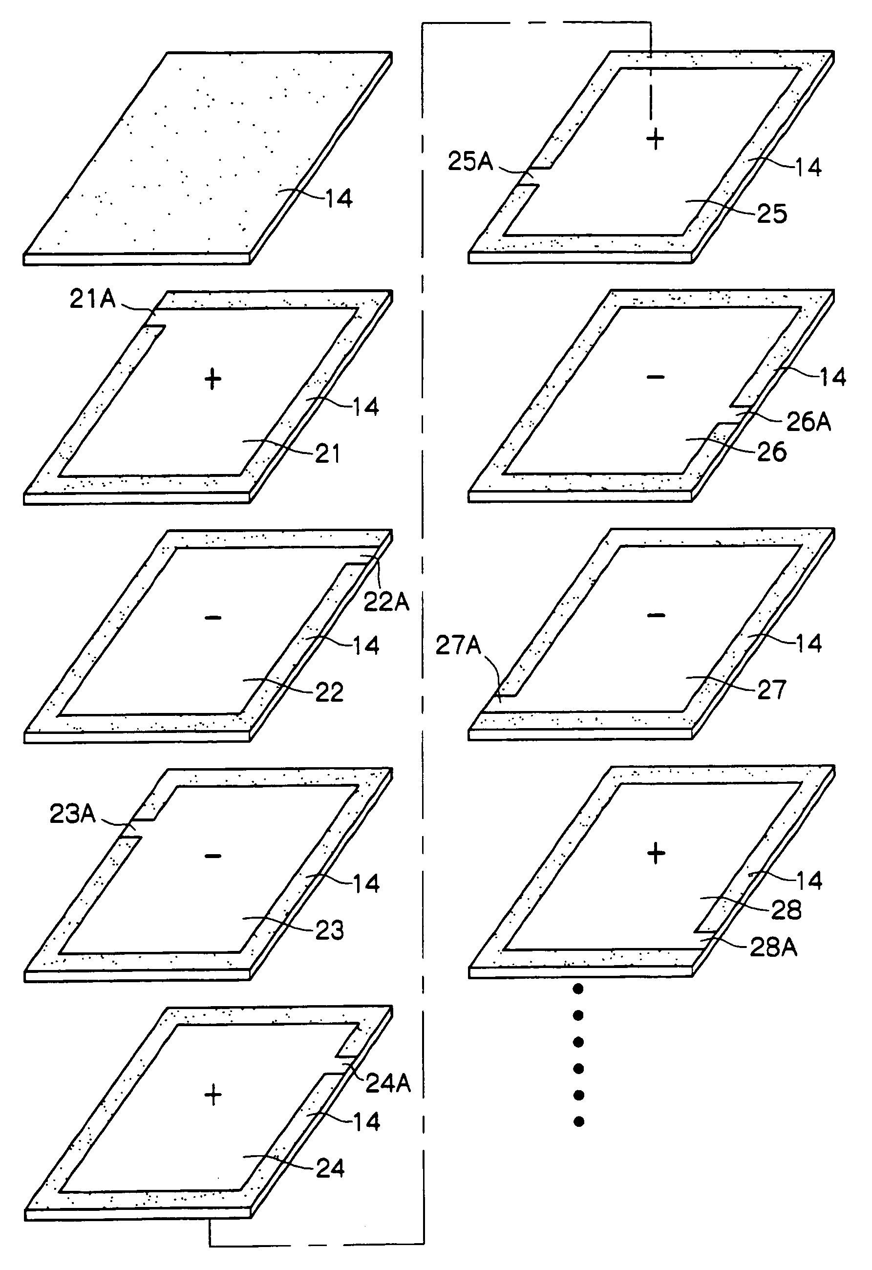
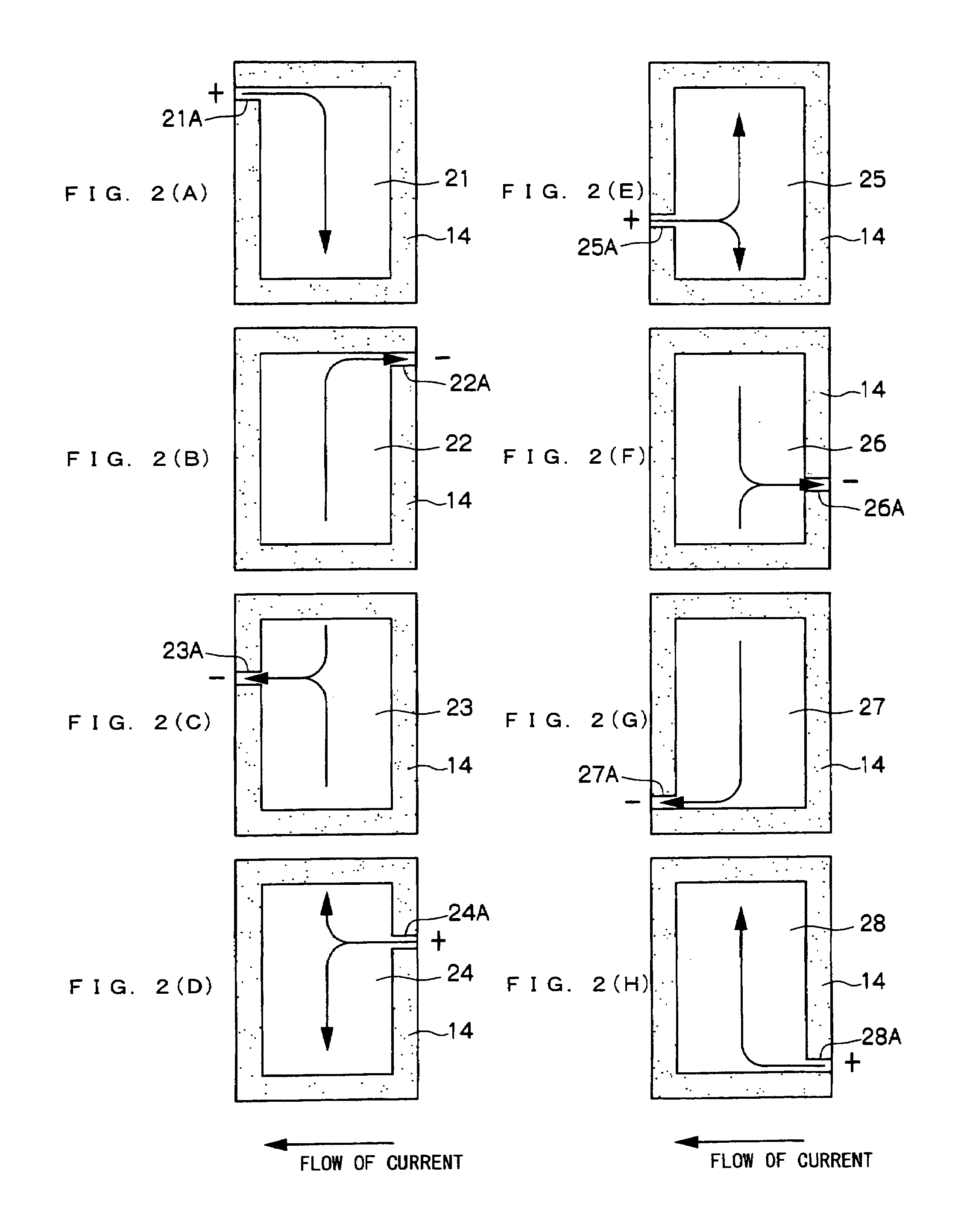
[0042]A multi-terminal multilayer capacitor 10 as a multilayer capacitor according to a first embodiment of the present invention is shown in FIG. 1 to FIG. 6. As shown in these drawings, the multi-terminal multilayer capacitor 10 according to this embodiment includes, as a main body portion thereof, a dielectric element 12 being a multilayer body in a rectangular parallelepiped shape that is obtained by sintering a stack of a plurality of ceramic green sheets which are dielectric sheets.

[0043]At a predetermined height position in the dielectric element 12 shown in FIG. 4, an internal electrode 21 in a planar shape is disposed, and a leadout portion 21A is led out from a back end portion on a left end side in FIG. 1 of the internal electrode 21. An internal electrode 22 also in a planar shape is disposed under the internal electrode 21 across a ceramic layer 14 in the dielectric element 12, and a leadout portion 22A is led out from a back end portion on a right end side in FIG. 1 of...


PUM

PropertyMeasurementUnit
polarityaaaaaaaaaa
electric currentsaaaaaaaaaa
equivalent series inductanceaaaaaaaaaa

Abstract

A multilayer capacitor includes: a dielectric element; a pair of first internal conductors with same polarity disposed in the dielectric element to be adjacent to each other while being separated from each other by the dielectric layer; first leadout portions led out from the pair of first internal conductors respectively, one being provided for each of the first internal conductors; a pair of second internal conductors with same polarity disposed in the dielectric element to be adjacent to each other while being separated from each other by the dielectric layer; and second leadout portions led out from the pair of second internal conductors respectively, one being provided for each of the second internal conductors, wherein the first leadout portion and the second leadout portion led out respectively from the first internal conductor and the second internal conductor disposed adjacent to each other are led out to substantially the same positions in side faces facing each other of the dielectric element, respectively. Therefore, a multilayer capacitor capable of reducing equivalent series inductance to reduce voltage fluctuation of a power source of a CPU is obtained.

Description

BACKGROUND OF THE INVENTION[0001]1. Field of the Invention[0002]The present invention relates to a multilayer capacitor that realizes reduced equivalent series inductance (ESL), and more particularly, to that suitable for use as a multi-terminal multilayer ceramic chip capacitor capable of reducing voltage fluctuation of a power source of a CPU.[0003]2. Description of the Related Art[0004]In recent years, due to an improved processing speed and a higher integration degree of a CPU (central processing unit) used for a data processor, its operating frequency is becoming higher and its current consumption is remarkably increasing. In accordance therewith, the operating voltage has been on the decreasing trend due to reduced power consumption. This has caused the occurrence of a higher-speed and larger current fluctuation in a power source for supplying power to the CPU, and it has become very difficult to control voltage fluctuation accompanying this current fluctuation, within an allo...

Claims


Application Information

Patent Timeline
Patent Type & Authority Patents(United States)
IPC IPC(8): H01G4/228H01G4/12H01G4/232H01G4/30H01G4/38H01G4/40
CPCH01G4/228H01G4/30Y10T29/43H01G4/232E06B3/9688E06B3/9648
Inventor TOGASHI, MASAAKI
Owner TDK CORPARATION
Why Eureka
Try Eureka