Phase rotator and data recovery receiver incorporating said phase rotator

a phase rotator and data recovery technology, applied in the direction of digital transmission, pulse automatic control, transmission, etc., can solve the problems of limiting data feeding, noisy environment in terms of power supply swing, substrate noise, etc., and achieve the effect of enhancing the stability margin

Inactive Publication Date: 2006-05-23
IBM CORP
View PDF2 Cites 18 Cited by
  • Summary
  • Abstract
  • Description
  • Claims
  • Application Information

AI Technical Summary

Benefits of technology

[0033]In general, some low pass filtering at the input may relax the filtering requirements of the low pass filter for the output channels, and the two filters (for input and output signals) will have the overall effect of one, more complex, filter.
[0041]In the preferred embodiments, the weighting coefficients are adapted to evolve controllably for effecting a phase shift in successive phase slices over a phase angle of 2π radians (360°) in a cyclic operation, thereby permitting an unlimited phase shift.
[0052]For each of the output channels, the weighting coefficient supply means preferably produces a same set of n weighting coefficients, the latter being applied at mutually staggered positions among the input channels of the output channels. This enables the number of different weighting coefficients to be kept small and hence more easily manageable.
[0059]Advantageously, the multiphase oscillating signal generator is outside the feedback loop. This generally enhances the stability margin in the feedback loop.

Problems solved by technology

With this growth in speed, a problem now resides at the level of link technology, which is becoming the limiting factor for feeding data into and out of a digital core.
In addition, such a chip performs digital functions which consume tens of Watts at few volts of power supply voltage, which means that tens of amps flow into and out of the chip at a few nano-seconds of cycle time.
This creates a very noisy environment in terms of power supply swing, substrate noise, etc.
Feedback control loops in general have a bandwidth limitation in the region of one tenth of the feedback frequency due to stability problems.
The approach described with reference to FIG. 1 is based on an analog control of the clock frequency and has an inherently limited jitter tracking bandwidth, but unlimited frequency tracking capability.

Method used


Image

  • Phase rotator and data recovery receiver incorporating said phase rotator
  • Phase rotator and data recovery receiver incorporating said phase rotator
  • Phase rotator and data recovery receiver incorporating said phase rotator

Examples


Embodiment Construction

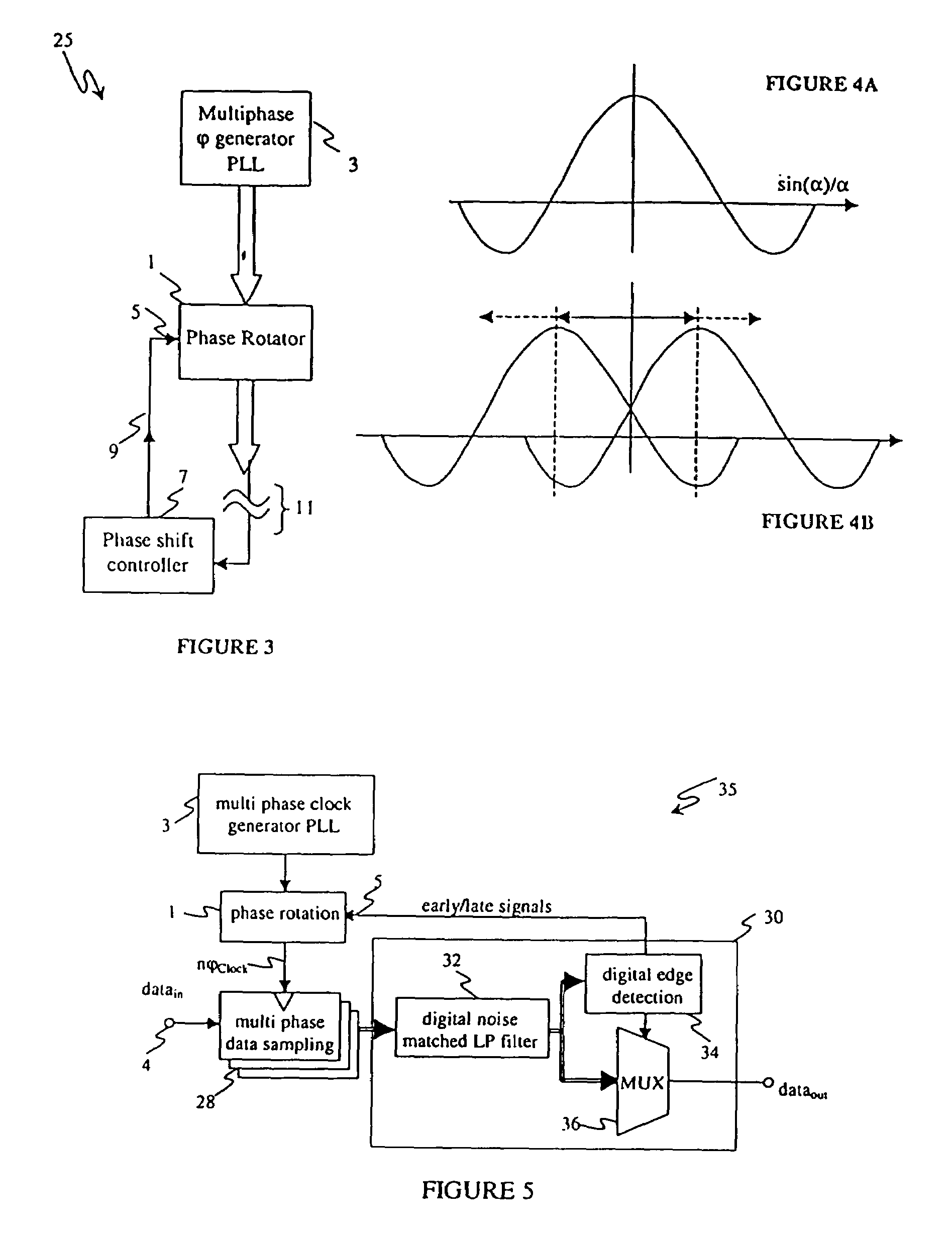
[0085]Referring now to the drawings, and more particularly to FIG. 3, there is shown a basic circuit implementation 25 of the phase rotator 1 in accordance with the invention. The phase rotator is here represented as a functional unit which receives at an input n phases from a multiphase clock generator phase-locked loop (PLL) 3, such as a ring oscillator, and in response produces a step-by-step adjustable, glitch-free modulo shift of those n phases. The number n of input phases is arbitrary, and can also be equal to 1. The phase shifted output can be delivered also as an n-phase clock signal, or a signal having a different number phases, for example 1 or n / 2 phases. Typically, the multiphase clock generator PLL is digital in nature, being based e.g. on a ring oscillator having tapped outputs corresponding to different phase slices of the clock signal.

[0086]The amount of shift is controllable through a control input 5 of the phase rotator. The control signal is typically in digital ...


PUM


Abstract

A phase rotator device for phase shifting an oscillating signal, including an input device having at least one input channel for receiving at least one phase of the oscillating signal and an output device having at least one output channel for delivering at least one phase of the oscillating signal with a controlled phase shift. For each output channel, the phase rotator includes a weighting device for weighting the value of the oscillating signal at each input channel by a respective weighting coefficient, and a summing device for summing the weighted signal values at each input channel and delivering the summed value as a shifted output phase at the output channel. Additionally, the phase rotator device includes a weighting coefficient supply device responsive to a phase shift control signal for controllably supplying evolving weighting coefficients to the weighting device, thereby to create a phase shift at the output channel.

Description

[0001]The present disclosure relates to subject matter contained in Japanese Patent Application No. EP00111369.5, filed May 26, 2000, which is expressly incorporated herein by reference in its entirety.BACKGROUND OF THE INVENTION[0002]1. Field of the Invention[0003]The present invention generally relates to a phase rotator device and to a data recovery receiver incorporating the phase rotator device, e.g. for use in digital data communications based on high speed wire link technology for high-speed digital switches involving clock and data recovery (CDR). More specifically, the invention concerns a phase rotator capable of producing a controlled phase shift, e.g. on a multiphase input clock signal, and a data recovery receiver incorporating such a phase rotator in a feedback control loop for synchronously tracking level transitions in a high-speed data stream.[0004]2. Description of the Related Art[0005]When performing CDR, conventional systems track possible phase variations in an ...

Claims


Application Information

Patent Timeline
Patent Type & Authority Patents(United States)
IPC IPC(8): H04L25/00H04L25/40H04L7/00H03L7/07H03L7/081H03L7/099H04L7/033H04L27/00H04L27/152
CPCH03L7/07H03L7/0814H03L7/0995H04L27/152H03L7/0998H04L2027/0059H04L7/0337
Inventor SCHMATZ, MARTIN
Owner IBM CORP
Why Eureka
Try Eureka