
Method and device for contactless measurement of a linear textile formation such as yarn etc

Inactive Publication Date: 2006-06-06
RIETER CZ AS
View PDF4 Cites 6 Cited by
  • Summary
  • Abstract
  • Description
  • Claims
  • Application Information

AI Technical Summary

Benefits of technology

[0008]An advantage of the invention exists in the fact that the measurement proper of the linear textile formation, i.e., without the subsequent integration of the individual values found by measurement, furnishes a value which by its character better reflects the actual parameters of the measured linear textile formation. This advantage permits an increase in the processing speed of individual measurements and simplifies the calculation algorithms for evaluating the measurement and interpreting the measurement results, thus reducing the requirements put on the device for measurement evaluation.
[0009]The device arranged in this way is easy to produce and to control, reliable in operation, and sufficient in precision. Another advantage of this device is in the increased surface of the radiation-sensitive elements of the radiation sensor as compared with the radiation-sensitive elements used in other radiation sensors. This advantage reduces the sensitivity of the radiation sensors to negative influences due to dust and permits a better-defined base point of the radiation-sensitive elements if such a base point exists and is required. Another advantage is the increased light sensitivity advantageously permitting, while maintaining the irradiation intensity of the sensor used in known sensors, the carrying out of measurements at speeds superior to those obtainable in measurements using square-shaped radiation-sensitive elements.
[0010]In one preferred embodiment, the radiation sensor is made as a CMOS optical sensor.
[0011]In another preferred embodiment, the radiation sensor consists of a CCD sensor.
[0012]Each of the two types of the radiation sensor is sufficiently precise and reliable for the device according to the invention. The advantage of the CMOS optical sensors over the CCD sensors consists in a more favorable measurement speed, in a more suitable and therefore more easily processable output signal, easier manufacture, and lower purchase cost. However, in spite of some drawbacks of the CCD sensors as compared with the CMOS optical sensors, the device equipped with the CCD sensor is sufficiently reliable and fully operative.
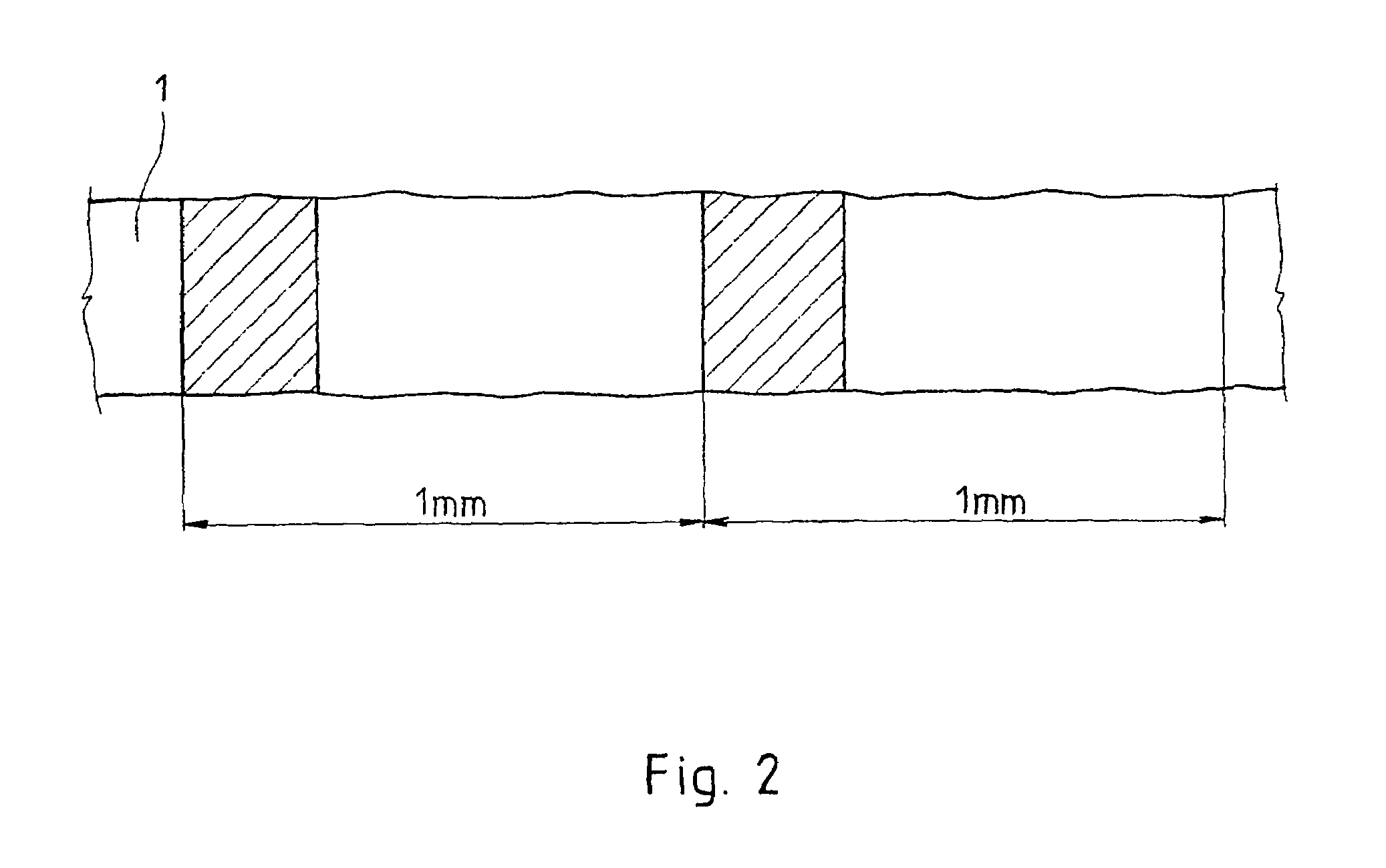
[0013]For obtaining the required measurement precision with sufficiently small size of the radiation-sensitive elements, it is advantageous if the radiation-sensitive elements are shaped as rectangular with dimensions in the direction of the motion of the measured linear textile formation between 15 μm and 200 μm.

Problems solved by technology

The drawback consists in that as a matter of fact only a minimum of the total length of the linear textile formation is really measured.
However, in view of both the dimensions of the radiation-sensitive elements which are in EP 0 122 475 A1 in the order of millimeters and of the design of the sensors, these sensors are unfit for use in the measurement of the parameters of a linear textile formation such as yarn, thread, textile fiber, silver, etc.

Method used


Image

  • Method and device for contactless measurement of a linear textile formation such as yarn etc
  • Method and device for contactless measurement of a linear textile formation such as yarn etc
  • Method and device for contactless measurement of a linear textile formation such as yarn etc

Examples


Embodiment Construction

[0019]Reference will now be made in detail to the presently presented embodiments of the invention, one or more examples of which are shown in the figures. Each example is provided to explain the invention, and not as a limitation of the invention. In fact, features illustrated or described as part of one embodiment can be used with another embodiment to yield still a further embodiment. It is intended that the present invention cover such modifications and variations.

[0020]The contactless measurement of a linear textile formation such as yarn, thread, textile fiber, sliver, etc., is carried out on various textile machine types such as open-end spinning machines, winding machines, etc.

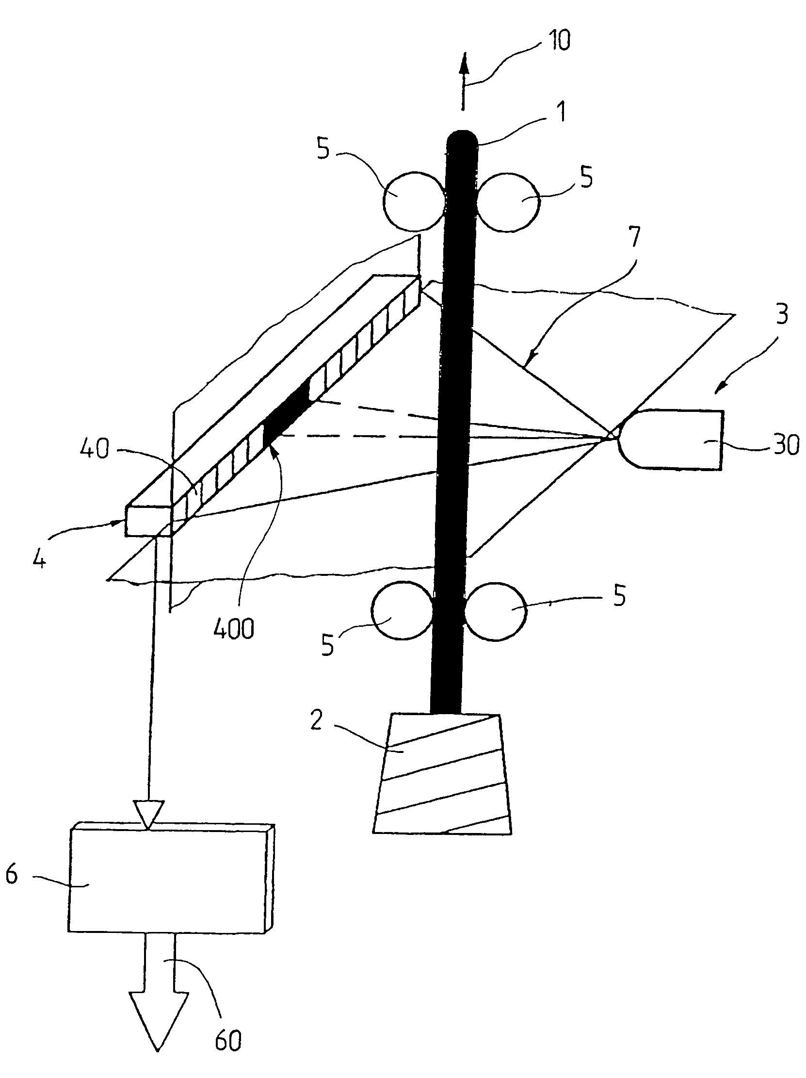
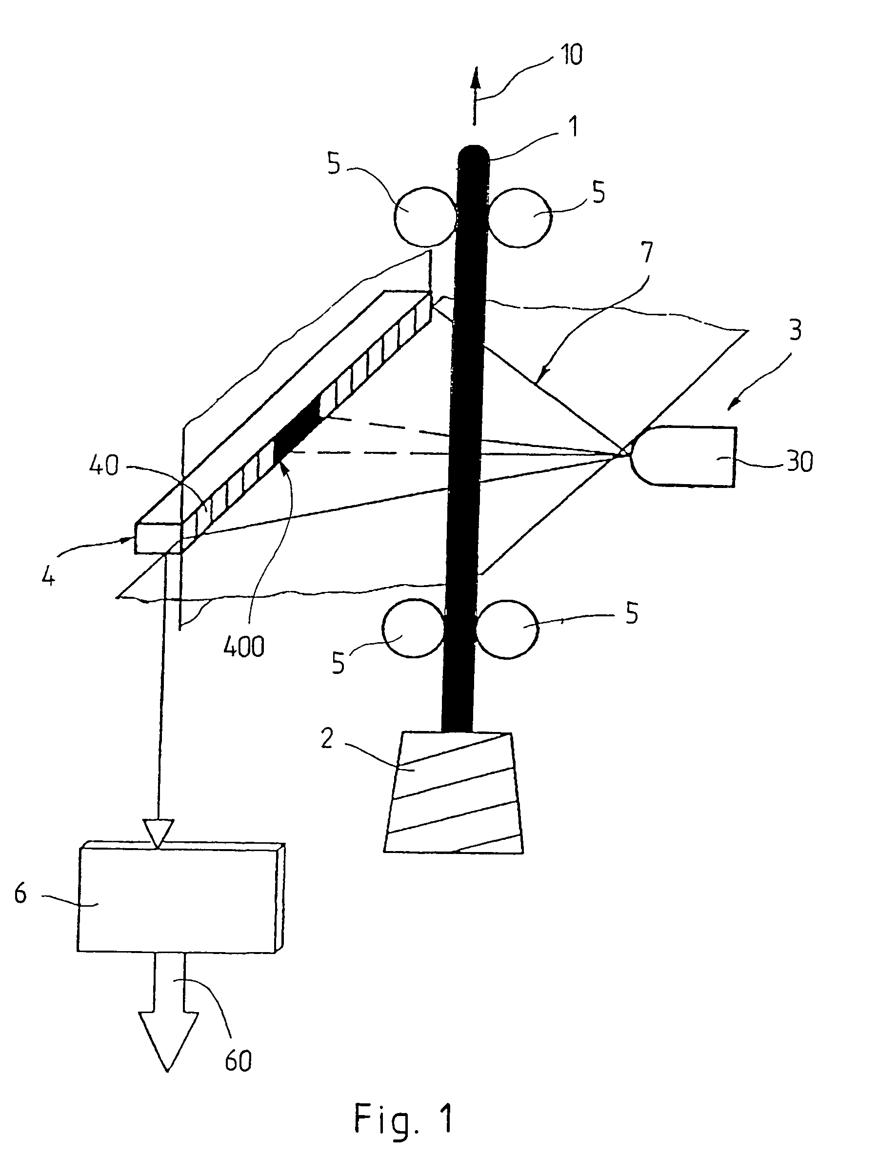
[0021]In the shown example of FIG. 1, the device for contactless measurement of a linear textile formation is used on an open-end spinning machine for measuring a yarn 1. However, the device can be suitably modified for use on other textile machines and for the measurement also of linear textile format...


PUM


Abstract

The invention relates to the contactless measurement of a linear textile formation such as yarn, thread, textile fiber, sliver, etc. in which a linear textile formation moves in a radiation flux between a radiation source and a radiation sensor consisting of a plurality of radiation-sensitive elements arranged next to each other in at least one row and in which the diameter and / or the hairiness and / or the density of the linear textile formation is determined on the basis of the number of overshadowed radiation-sensitive elements of the radiation sensor and / or on the basis of the irradiation degree of the radiation-sensitive elements. In order to measure a high degree of the total length of the moving textile formation it is proposed to match the dimensions of the radiation-sensitive elements such that the dimension of the radiation-sensitive elements of the radiation sensor in the direction of the motion of the measured linear textile formation is superior to their dimension in the direction normal to the direction of the motion of the measured linear textile formation.

Description

FIELD OF THE INVENTION[0001]The invention relates to a device for contactless measurement of parameters of a linear textile formation (1) such as yarn, thread, textile, fiber, silver, etc. The device includes a radiation source, a radiation sensor which has a plurality of radiation-sensitive elements arranged in at least one row, and an evaluation device connected with the radiation sensor. The device also has an output of information on the monitored parameters of the linear textile formation. The device is arranged in such a manner that the linear textile formation is movable along its longitudinal axis in the direction of its motion and is movable in the radiation flux between the radiation source and the radiation sensor with the row of radiation-sensitive elements being arranged perpendicular to the direction of motion.BACKGROUND OF THE INVENTION[0002]WO 99 / 36746 discloses a device for contactless measurement of parameters of a linear textile formation such as yarn, thread, tex...

Claims


Application Information

Patent Timeline
IPC IPC(8): G01B11/10G01N21/89G01N21/952
CPCG01B11/105G01N21/952G01N21/8915
Inventor STUSAK, MIROSLAV
Owner RIETER CZ AS
Learn More