Apparatus and method for wavelength-locked loops for systems and applications employing electromagnetic signals

a technology of electromagnetic signals and wavelengthlocked loops, applied in the field of electromagnetic signal apparatus and method, can solve the problems of inability to achieve the effect of reducing the number of laser devices, and affecting the efficiency of laser devices

Inactive Publication Date: 2006-06-13
IBM CORP
View PDF54 Cites 17 Cited by
  • Summary
  • Abstract
  • Description
  • Claims
  • Application Information

AI Technical Summary

Benefits of technology

[0008]It is an object of the present invention to provide a servo-control “wavelength-locked loop” circuit that enables real time mutual alignment of an electromagnetic signal having a peaked spectrum function including a center wavelength and a wavelength selective device implementing a peaked passband function including a center wavelength, in a system employing electromagnetic waves.
[0010]It is a further object of the present invention to provide a wavelength-locked loop for an optical system that enables real time alignment and tracking of any spectral device that selects a wavelength, such as a Bragg grating, in optical fibers and waveguides, etc., for use in WDM systems.
[0013]It is still another object of the present invention to provide a servo / feedback loop for an optical system, referred to as a “wavelength-locked loop,” that enables real time alignment and tracking of laser center wavelengths and filter passband center wavelengths in multi-gigabit laser / optical systems such that the optical loss of a WDM filter / laser combination is greatly reduced, thereby enabling significantly larger link budgets and longer supported distances.
[0014]It is yet still another object of the present invention to provide a servo / feedback loop for an optical system, referred to as a “wavelength-locked loop,” that enables real time alignment and tracking of laser center wavelengths and filter passband center wavelengths in multi-gigabit laser / optical systems such that lower cost lasers and filters may be used providing a significant cost reduction in the WDM equipment.
[0018]Alternately, the system and method of the invention may be implemented to tune such devices for WDM and optical network applications, in real-time, during manufacture, e.g., tuning all lasers to a specific wavelength. This would significantly increase lot yields of laser devices which otherwise may be discarded as not meeting wavelength specifications as a result of manufacture process variations, for example.

Problems solved by technology

In commercial systems used today, however, it is very difficult to perform this alignment—lasers and filters are made by different companies, and it is both difficult and expensive to craft precision tuned optical components.
As a result, the systems in use today are far from optimal; optical losses in a WDM filter can be as high as 4 db due to misalignment with the laser center wavelength (the laser's optical power is lost if it cannot pass through the filter).
This has a serious impact on optical link budgets and supported distances, especially since many filters must be cascaded together in series (up to 8 filters in current designs, possibly more in the future).
If every filter was operating at its worst case condition (worst loss), it would not be possible to build a practical system.
Furthermore, the laser center wavelengths drift with voltage, temperature, and aging over their lifetime, and the filter characteristics may also change with temperature and age.
This problem places a fundamental limit on the design of future WDM networking systems.
A second, related problem results from the fact that direct current modulation of data onto a semiconductor laser diode causes two effects, which may induce rapid shifts in the center wavelength of the laser immediately after the onset of the laser pulse.
Not only can these effects cause laser center wavelengths to change rapidly and unpredictably, they also cause a broadening of the laser linewidth, which can be a source of loss when interacting with optical filters or may cause optical crosstalk.
Avoiding these two effects requires either non-standard, expensive lasers, external modulators (which are lossy and add cost), or driving the laser at less than its maximum power capacity (which reduces the link budget and distance).
Lowering the data modulation rate may also help, but is often not an option in multi-gigabit laser links.

Method used


Image

  • Apparatus and method for wavelength-locked loops for systems and applications employing electromagnetic signals
  • Apparatus and method for wavelength-locked loops for systems and applications employing electromagnetic signals
  • Apparatus and method for wavelength-locked loops for systems and applications employing electromagnetic signals

Examples


Embodiment Construction

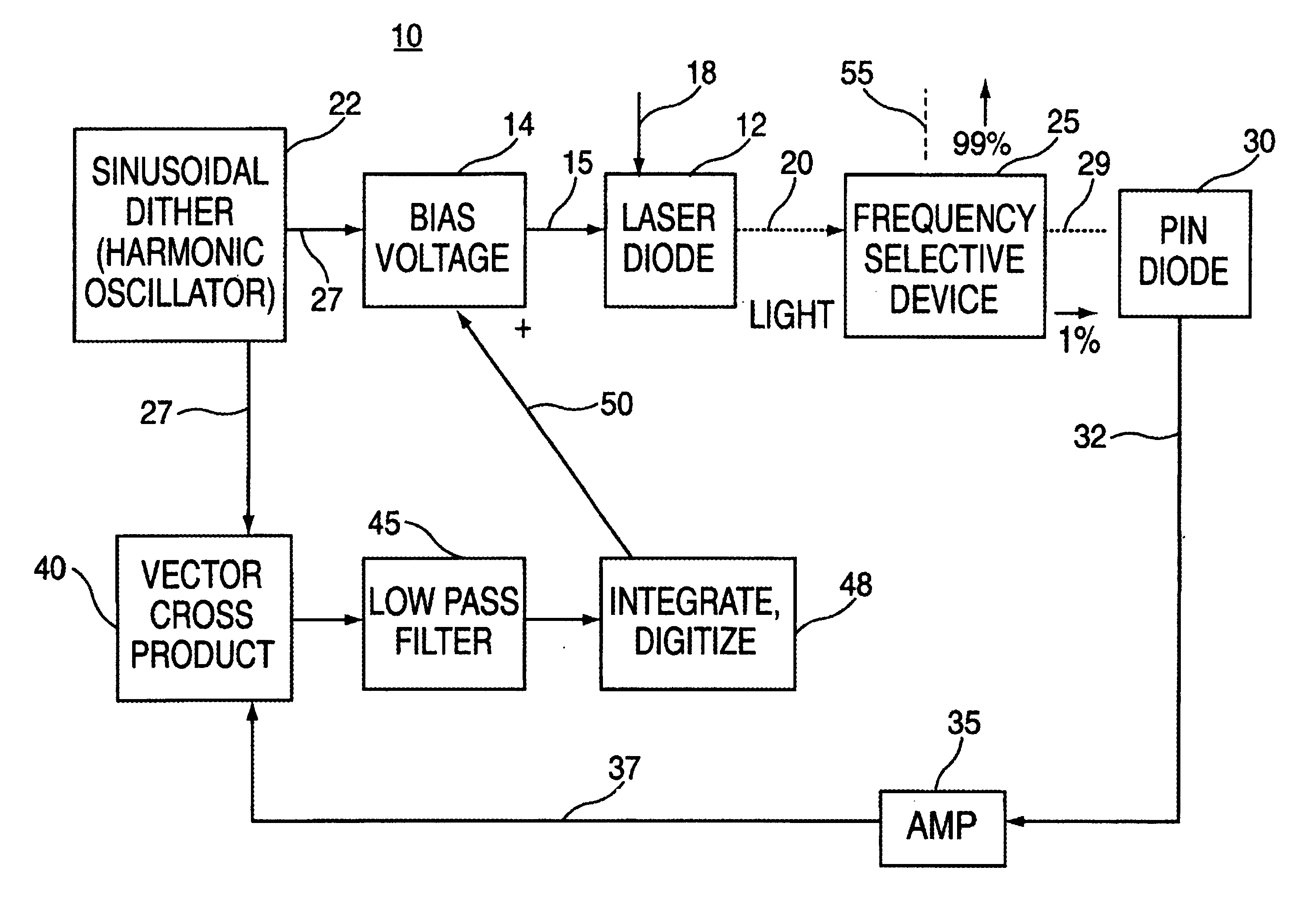
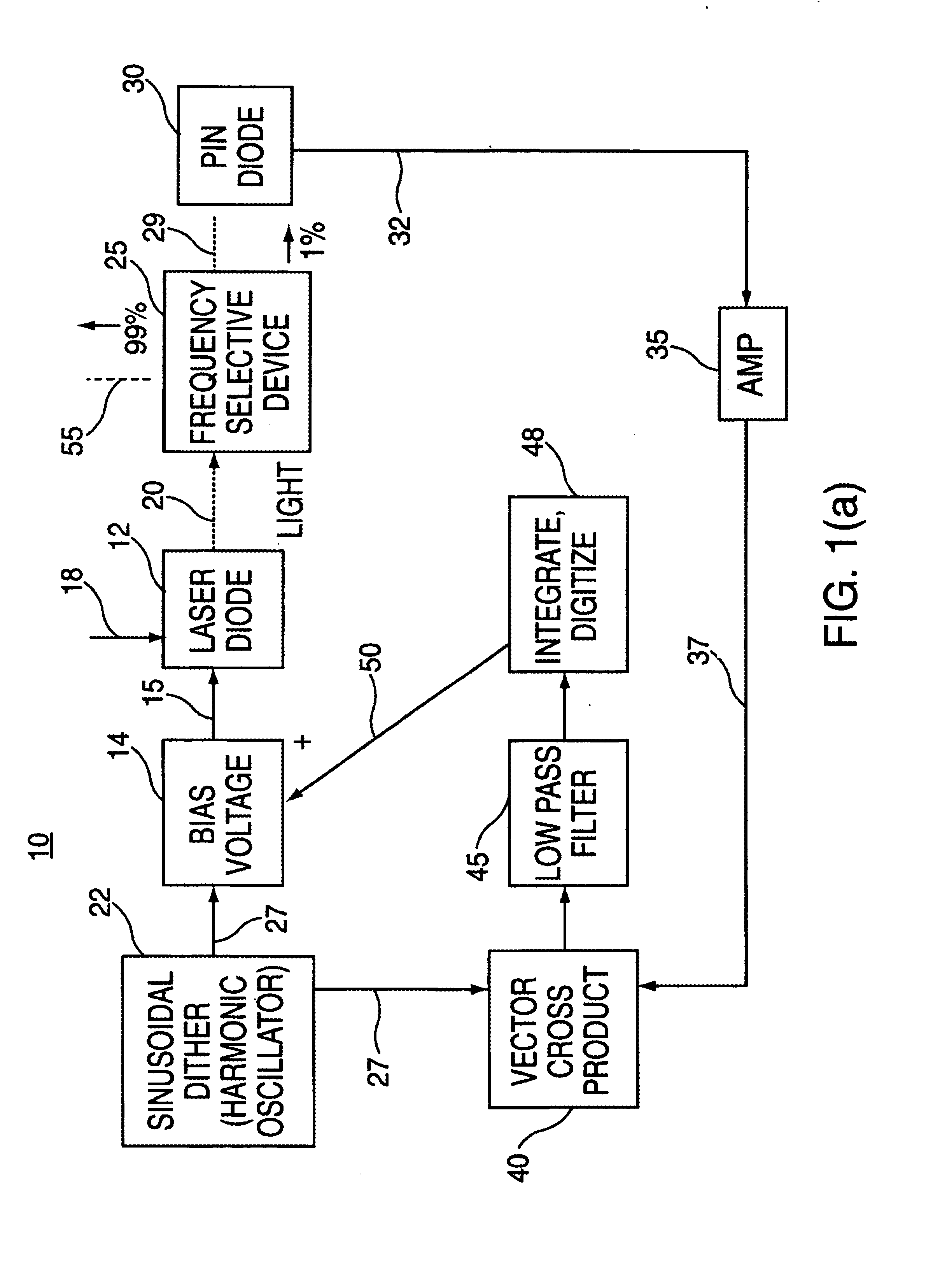
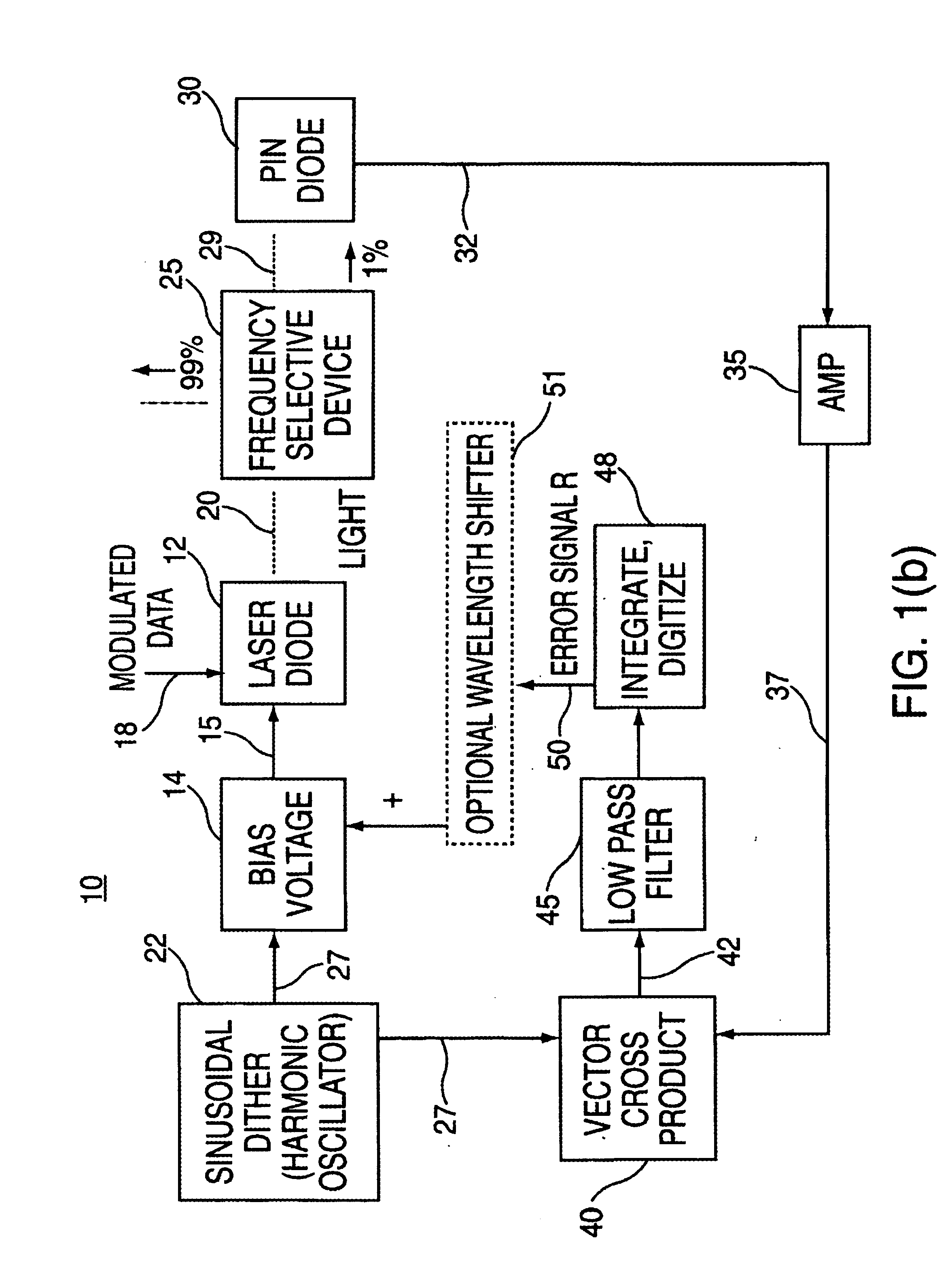
[0032]The present invention is a novel servo-control system implemented for optical systems including light sources, such as lasers, and frequency selective devices, such as bandpass filters. The servo-control system, herein referred to as the “wavelength-locked loop” or “lambda-locked loop” (since the symbol lambda is commonly used to denote wavelength), implements a dither modulation to continuously adjust an electromagnetic signal source characterized as having a peaked frequency spectrum or peaked center wavelength, e.g., laser light, so as to track the center of a frequency selective device, e.g. a filter passband. In this manner, optimal power of the signal is transmitted and optimal use is made of the system transmission bandwidth.

[0033]The basic operating principle of the wavelength-locked loop (WLL) is now described with reference to FIG. 1(a), which depicts an example optical system 10 including a light source such as laser diode 12 driven with both a bias voltage 15 from ...


PUM


Abstract

A wavelength-locked loop servo-control circuit and methodology that enables real time mutual alignment of an electromagnetic signal having a peaked spectrum function including a center wavelength and a wavelength selective device implementing a peaked passband function including a center wavelength, in a system employing electromagnetic waves. The circuit comprises a mechanism for applying a dither modulation signal at a dither modulation frequency to the electromagnetic signal, and inputting the dither modulated electromagnetic signal to the wavelength selective device; a mechanism for converting a portion of the dither modulated electromagnetic signal to an electric feedback signal; a mechanism for continuously comparing the feedback signal with said dither modulation signal and generating an error signal representing a difference between a frequency characteristic of the feedback signal and a dither modulation frequency; and a mechanism for adjusting the peaked spectrum function of the electromagnetic signal according to the error signal. The center wavelength of the electromagnetic signal and the wavelength selective device center wavelength become aligned when the frequency characteristic of the feedback signal is two times the dither modulation frequency.

Description

BACKGROUND OF THE INVENTION[0001]1. Field of the Invention[0002]The present invention relates generally to systems that generate and process electromagnetic signals in the radio frequency, microwave and optical frequency spectra, and particularly to a novel servo-control circuit for such systems employing such electromagnetic signals that teaches the principle of wavelength-locked loops for optimizing signal power and transmission bandwidth through such systems.[0003]2. Description of the Prior Art[0004]Wavelength Division Multiplexing (WDM) and Dense Wavelength Division Multiplexing (DWDM) are light-wave application technologies that enable multiple wavelengths (colors of light) to be paralleled into the same optical fiber with each wavelength potentially assigned its own data diagnostics. Currently, WDM and DWDM products combine many different data links over a single pair of optical fibers by remodulating the data onto a set of lasers, which are tuned to a very specific wavelengt...

Claims


Application Information

Patent Timeline
IPC IPC(8): H01S3/098H04B1/04H04B10/00H04B10/25H04J14/00H04J14/02
CPCH04B10/572H04B10/506H01S5/06832H04B10/00H04B10/25
Inventor DECUSATIS, CASIMER M.JACOBOWITZ, LAWRENCE
Owner IBM CORP
Why Eureka
Try Eureka