
First and second derivative processing of wavelength multiplexed optical signals

Active Publication Date: 2006-06-13
IBM CORP
View PDF48 Cites 19 Cited by
  • Summary
  • Abstract
  • Description
  • Claims
  • Application Information

AI Technical Summary

Benefits of technology

[0009]It is therefore an object of the present invention to provide a system and method for automatically improving signal detection sensitivity in WDM and DWDM systems.
[0011]It is a further object of the present invention to provide a system and method for implementing derivative measurement techniques for increasing signal detection sensitivity in WDM and DWDM systems that employs a servo-control loop that enables dynamic tracking of the center wavelength of an optical signal to the peak of an optical filter passband.
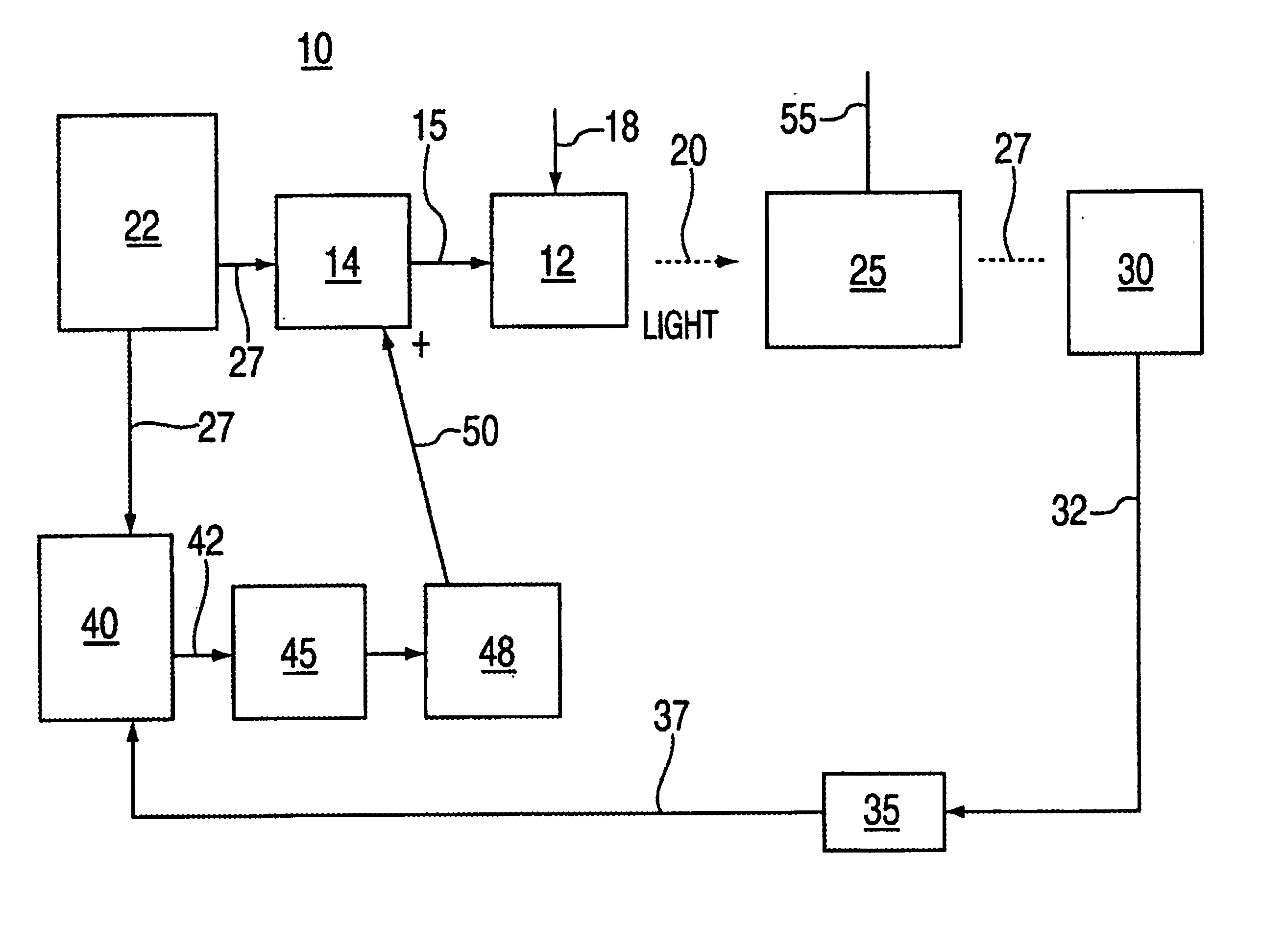
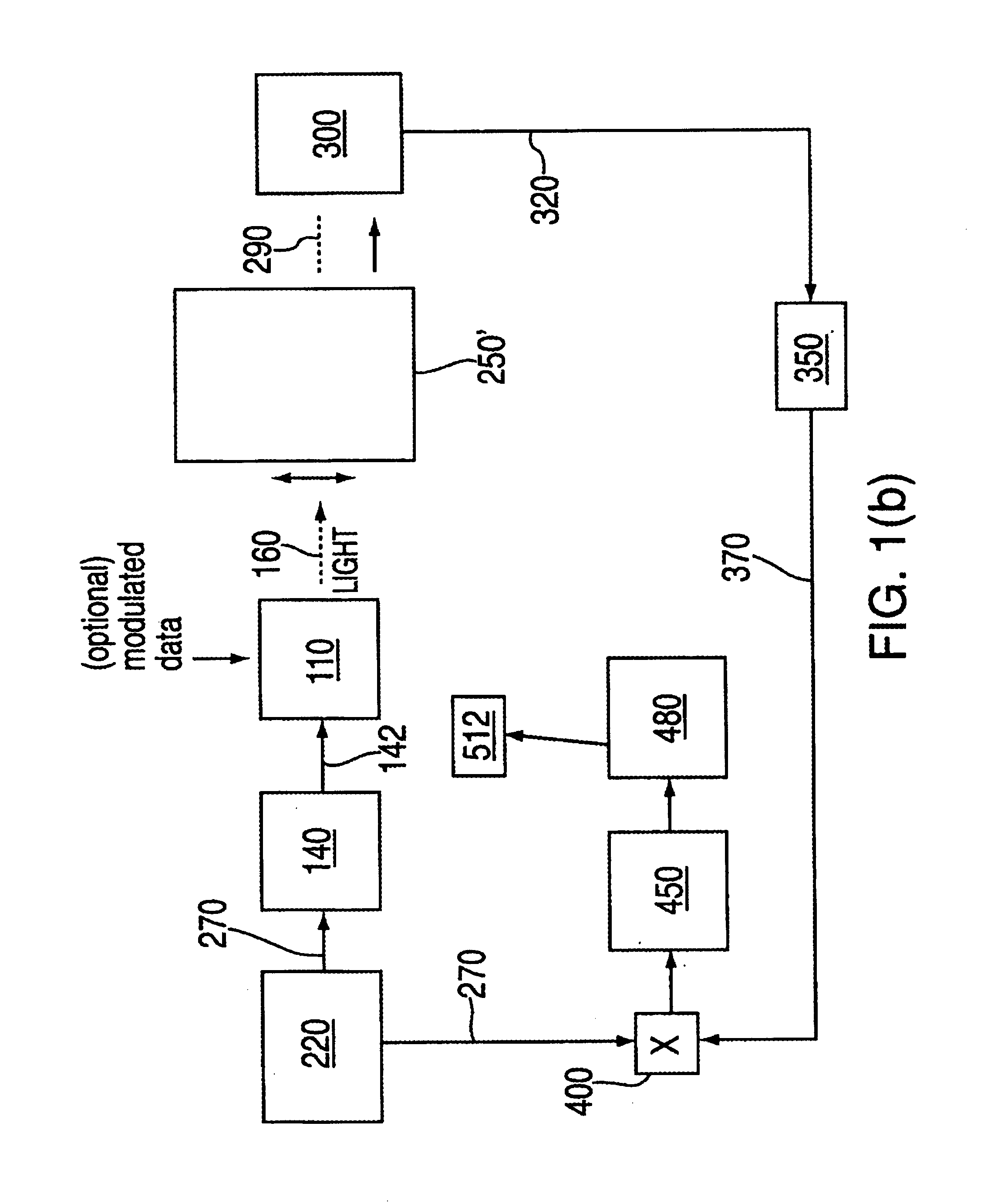
[0013]Thus, according to one aspect of the invention, there is provided a system and method for detecting optical signals in optical networks comprising: an optical signal generator for generating optical signals, each optical signal having a peaked spectrum function including a center wavelength for transmission over a communication channel; a mechanism for applying a dither modulation signal at a dither modulation frequency to the optical signal about the center wavelength; and, a wavelength-locked loop servo-control circuit for detecting a rate of change of an intensity of the dither modulated optical signal with respect to the center wavelength, the detected rate of change indicating a degree of optical attenuation in a communication system at that wavelength. The wavelength-locked loop servo-control circuit further enables real-time adjustment of the optical signal center wavelength in a manner so as to minimize optical signal attenuation in the communication channel.

Problems solved by technology

Weak signals at the wavelength of interest may also be nested in broadband background noise, which also limits their detection by decreasing ambient signal-to-noise ratio.
This problem is additionally pertinent to spectroscopy and other forms of optical signal processing equipment.

Method used


Image

  • First and second derivative processing of wavelength multiplexed optical signals
  • First and second derivative processing of wavelength multiplexed optical signals
  • First and second derivative processing of wavelength multiplexed optical signals

Examples


Embodiment Construction

[0025]The present invention is directed to techniques for measuring the optical loss of a communication channel due to absorption, impurities, or crosstalk, for example, at specified wavelength by determining either the first or second derivative of the fiber or channel's optical transmission curve with respect to the wavelength. This is due to the recognition that the derivative output signal is directly proportional to the optical loss in the wavelength communication channel. This invention is particularly directed to a system and method for implementing derivative measurement techniques by employment of a novel servo-control system in practical optical signal processing equipment, e.g., equipment compatible with existing WDM and DWDM network equipment.

[0026]The explanations herein discuss both wavelength and frequency, which have a reciprocal relationship (λ=c / f, where c=speed of light), as is well known in the field of optics.

[0027]As shown in FIG. 2(a), the novel servo-control ...


PUM


Abstract

A system and method for optimizing performance characteristics of optical networks. The system and method exploits a wavelength-locked loop servo-control circuit and methodology that enables real time adjustment of optical signals in accordance with attenuation characteristics of an optical transmission channel. Particularly, the invention enables alignment of optical signal center wavelengths and optical wavelength selective devices exhibiting a peaked passband function in optical networks utilizing information included in first derivative and second derivatives of dither modulated optical signals extracted from a feedback signal provided in the wavelength-locked loop servo-control circuit.

Description

BACKGROUND OF THE INVENTION[0001]1. Field of the Invention[0002]The present invention relates generally to optical devices such as lasers, and fiber optic data transmission systems employing the same, and particularly to a novel wavelength-locked loop servo-control circuit for optimizing performance of optical signal processing equipment, especially equipment employed in wavelength division multiplexing (WDM) systems and dense wavelength division multiplexing (DWDM) systems.[0003]2. Description of the Prior Art[0004]Wavelength Division Multiplexing (WDM) and Dense Wavelength Division Multiplexing (DWDM) are light-wave application technologies that enable multiple wavelengths (colors of light) to be paralleled into the same optical fiber with each wavelength potentially assigned its own data diagnostics. Currently, WDM and DWDM products combine many different data links over a single pair of optical fibers by re-modulating the data onto a set of lasers, which are tuned to a very spec...

Claims


Application Information

Patent Timeline
IPC IPC(8): H04B10/08H04B10/04H04J14/02H04B10/158
CPCH04B10/697
Inventor JACOBOWITZ, LAWRENCEDECUSATIS, CASIMER M.
Owner IBM CORP
Learn More