Ink jet recording head, manufacturing method therefor, and substrate for ink jet recording head manufacture

Inactive Publication Date: 2006-06-20
CANON KK
View PDF18 Cites 29 Cited by
  • Summary
  • Abstract
  • Description
  • Claims
  • Application Information

AI Technical Summary

Benefits of technology

[0032]Further, in the case of the ink jet recording head manufacturing method which employs the ink jet recording head substrate in accordance with the present invention, the edge of the ink supply hole, on the obverse side of the substrate, results from the edge of the groove formed from the obverse side of the substrate. Therefore, using this ink jet recording head manufacturing method makes it possible to precisely position the edge of the ink supply hole, on the obverse side of the substrate, relative to the other structural components, for example, the ejection pressure generation elements which are present on the surface of the substrate on the obverse side, since the edge of the groove formed from the obverse side can be positioned directly relative to these structural components.
[0033]As will be evident from the above description, using the ink jet recording head substrate in accordance with the present invention makes it possible to manufacture an ink jet recording head the nozzles of which are uniform in ink passage conductance and are quickly and reliably refilled.
[0034]Further, the recess portion, immediately next to the edge of the ink supply hole, formed by forming a groove from the obverse side of the substrate, is covered with the protective film. Therefore, it is highly resistant to the corrosiveness of ink. Further, an anisotropic etching method, which creates a groove with a surface having a crystal orientation index of <111>, which is higher in resistance to the corrosiveness of alkaline substances, is used as the etching method for forming the groove from the reverse side of the substrate. Therefore, the surface of the ink supply hole is highly resistant to the corrosiveness of ink. In other words, using the ink jet recording head substrate in accordance with the present invention makes it possible to manufacture an ink jet recording head the entirety of which is highly resistant to the corrosiveness of ink.
[0035]The groove(s) to be formed in the obverse surface of the ink jet recording head substrate in accordance with the present invention may be in the form of a single (or two) relatively long groove(s) which extends in the adjacencies of a plurality of rows of e

Problems solved by technology

Japanese Laid-open Patent Application 6-238904, however, does not disclose a method for protecting the surface of the ink supply hole, that is, the surface of the groove, although it discloses the above described method for forming the through hole, as the ink supply hole, through the substrate by merging the groove formed from the obverse side of the substrate, with the groove formed from the reverse side.
Thus, if an ordinary silicon wafer is used as the substrate for an ink jet recording head, an ordinary method for forming an ink supply hole is not satisfactory to make the lateral surfaces of the ink supply hole, that is, silicon surfaces, resistant to corrosive ink such as alkaline ink.
Therefore, it is very difficult to form this ridge to match a predetermined pattern.
This problem is not limited to an anisotropic etching method.
That is, even if a wet etching method is employed, the ridge resulting from the angular merging of the two surfaces is likely to be etched at a higher rate than the other portion of the substrate, making it very difficult to give the ridge the predetermined configuration.
Further, although Japanese Laid-open Patent Applications 10-34928 and 10-95119 disclose the ink supply hole forming method in which the substrate is shaved, on the obverse side, across the areas where ejection pressure generation elements have been formed, in order to make lower the areas other than where the ejection pressure generation elements have been formed, and then, a through hole is formed from the reverse side of the substrate so that the through hole reaches the shaved portion of the substrate, these documents do

Method used


Image

  • Ink jet recording head, manufacturing method therefor, and substrate for ink jet recording head manufacture
  • Ink jet recording head, manufacturing method therefor, and substrate for ink jet recording head manufacture
  • Ink jet recording head, manufacturing method therefor, and substrate for ink jet recording head manufacture

Examples


Example

Embodiment 1

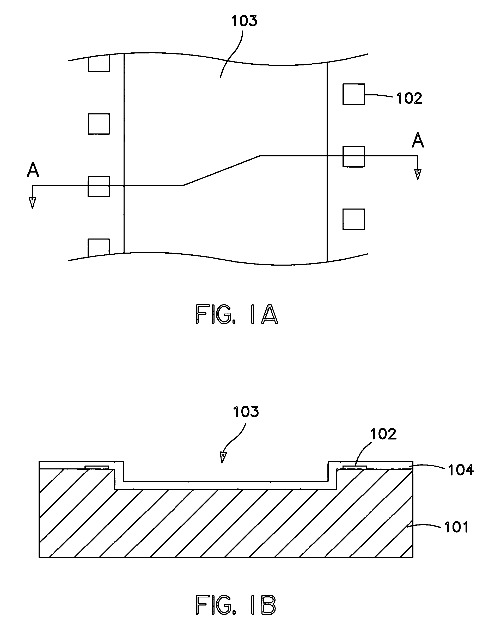
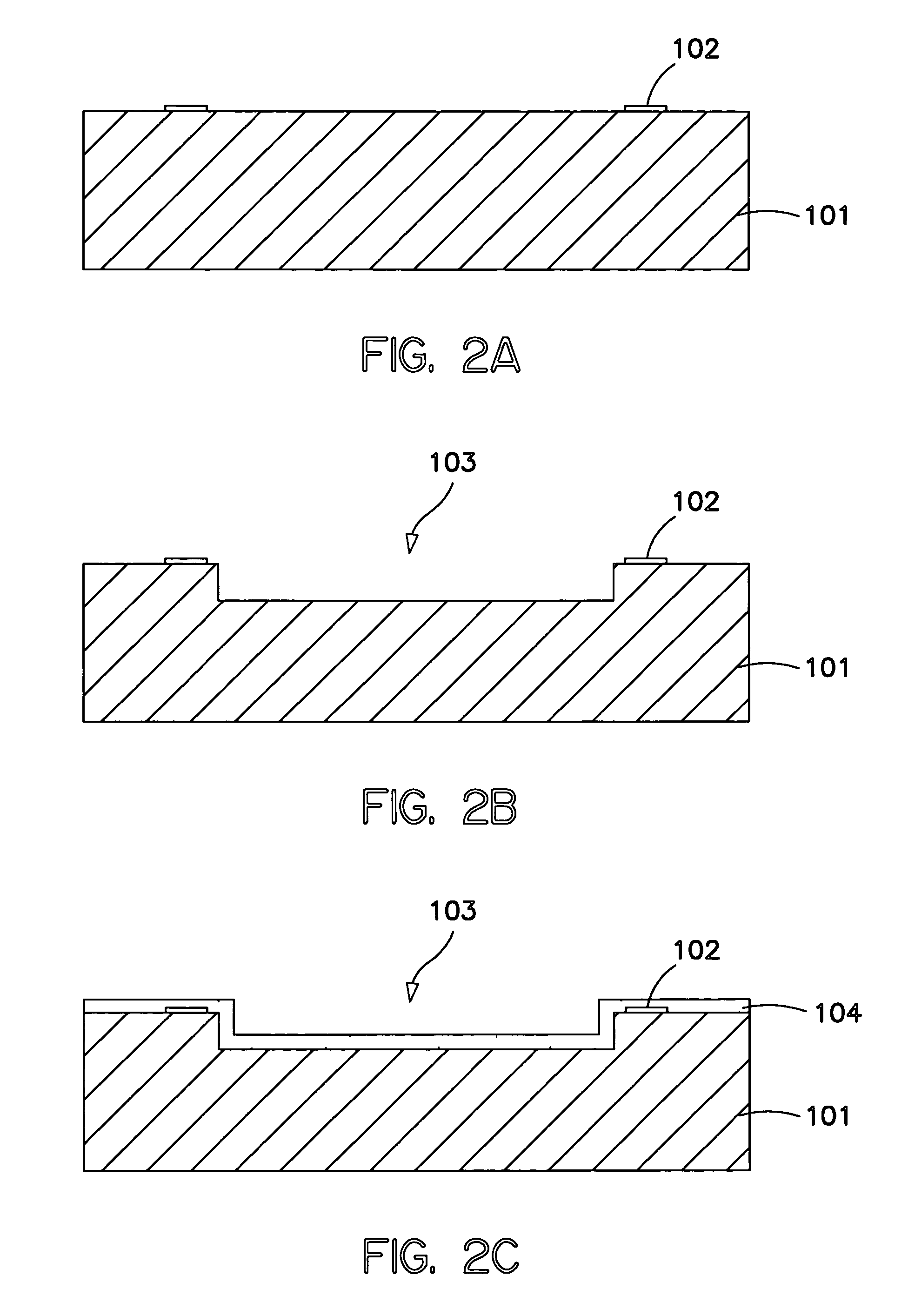
[0072]Referring to FIGS. 1A–3D, the ink jet recording head manufacturing method in the first embodiment of the present invention will be described. FIGS. 2A–3D are schematic drawings of the ink jet recording head, sequentially showing the ink jet recording head manufacturing steps, and FIGS. 1A and 1B are schematic drawings of the ink jet recording head substrate which has been completed through the step shown in FIG. 2A to the step shown in FIG. 2C; FIG. 1A is a plan view thereof, and FIG. 1B is a sectional view thereof at the line A—A in FIG. 1A. Each of the drawings in FIGS. 2A–3D is a sectional view of the substrate at a line comparable to the line A—A in FIG. 1A.

[0073]Referring to FIG. 1A, the ink jet recording head manufactured using the ink jet recording head manufacturing method in this embodiment has a substrate 101 on which a plurality of ejection pressure generation elements 102 for generating the pressure for ejecting ink (liquid) were formed. The substrate 1...

Example

[0092]Next, referring to FIGS. 4A and 4B, the second embodiment of the present invention will be described. FIGS. 4A and 4B are schematic drawings of the ink jet recording head substrate in this embodiment, after the completion of the manufacturing steps from the first step to the step comparable to the step shown in FIG. 2C; FIG. 4A is a plan view thereof, and FIG. 4B is a sectional view thereof at the line A—A in FIG. 4A.

[0093]In this embodiment, the recess 203 is formed by an anisotropic etching method. With the use of this etching method, the lateral walls of the recess 203 become slanted. The ink jet recording head manufacturing steps in this embodiment other than the step for forming the recess 203 are the same as those in the first embodiment.

[0094]Therefore, the ink jet recording head manufactured with the use of the ink jet manufacturing method in this embodiment is virtually identical to that manufactured with the use of the method in the first embodiment, except that the ...

Example

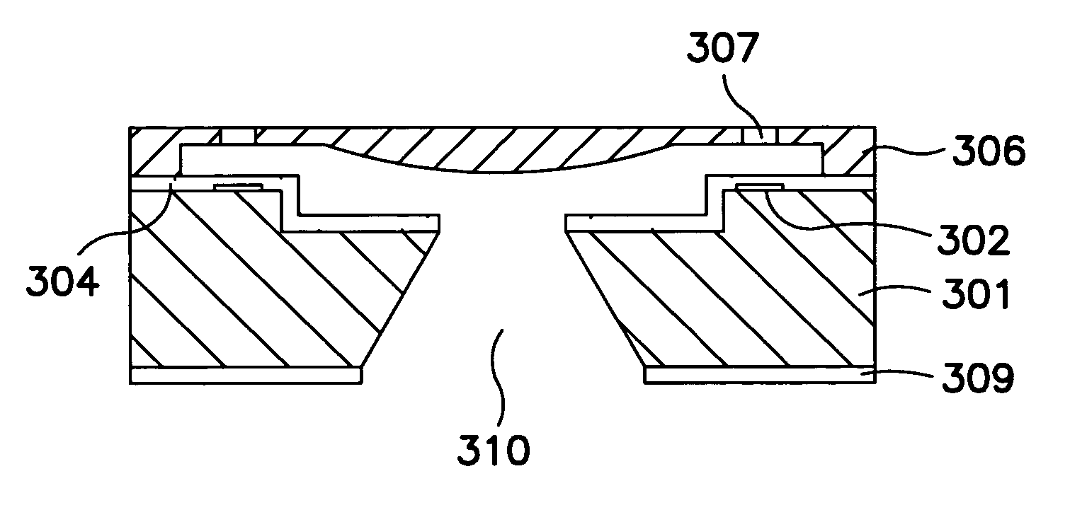
[0097]Next, referring to FIGS. 5A–6B, the third embodiment of the present invention will be described. FIGS. 5A and 5B are schematic drawings of the ink jet recording head substrate in this embodiment, after the completion of the manufacturing steps from the first step to the step comparable to the step in the first embodiment shown in FIG. 2C; FIG. 5A is a plan view thereof, and FIG. 5B is a sectional view thereof at the line A—A in FIG. 5A. FIGS. 6A and 6B are schematic drawings of the completed ink jet recording head; FIG. 6A is a horizontal sectional view thereof, and FIG. 6B is a vertical sectional view thereof at the plane A—A in FIG. 6A.

[0098]Referring to FIG. 5A, the recess 303 in this embodiment has a plurality of rectangular appendages extending toward the ejection pressure generation elements, one for one. Thus, after the formation of the recess 303 in the obverse surface of the substrate, the remaining portion of the obverse surface of the substrate is shaped so that it ...


PUM

PropertyMeasurementUnit
Pressureaaaaaaaaaa
Photosensitivityaaaaaaaaaa
Anisotropyaaaaaaaaaa

Abstract

A base member for use in manufacturing an ink jet recording head, which includes a supply port, an ejection outlet, a liquid flow path for directing liquid supplied from the supply port to the ejection outlet, and an ejection pressure generating element, disposed in the liquid flow path, for ejecting the liquid. The supply port is formed as a through-opening in a substrate on which the ejection pressure generation element is provided. The base member includes a recessed portion formed on the side of the substrate provided with the ejection pressure generation. The recessed portion extends from an edge of the supply port to a neighborhood of the ejection pressure generation element. A protection layer is provided at least on a portion of the substrate surface constituting the recessed portion.

Description

BACKGROUND OF THE INVENTIONField of the Invention[0001]The present invention relates to an ink jet recording head, a manufacturing method therefor, and a substrate for ink jet recording head manufacture.[0002]Generally, an ink jet recording head used for an ink jet recording method (liquid ejection recording method) comprises: a plurality of minute holes (which hereinafter will be referred to as orifices) from which liquid (ink) is ejected; a plurality of liquid passages leading to the plurality of orifices; and a plurality of ejection pressure generating portions disposed in the liquid passages to generate the pressure for ink ejection. In order to produce high quality images with the use of this type of ink jet recording head, it is desired that the plurality of orifices are uniform, and remain consistent, in the volume of ink which is ejected from an orifice, and the speed at which ink is ejected from an orifice. One of the recording methods capable of achieving this objective is...

Claims


Application Information

Patent Timeline
IPC IPC(8): C03C15/00B41J2/16
CPCB41J2/1603B41J2/1628B41J2/1629B41J2/1642B41J2/1632B41J2/1634B41J2/1639B41J2/1631B41J2/16
Inventor HAYAKAWA, KAZUHIROTERUI, MAKOTO
Owner CANON KK
Why Eureka
Try Eureka