Gasket for fuel cell and method of forming it

a fuel cell and gasket technology, applied in the field of gaskets for fuel cells, can solve the problems of obstructing the formation of gaskets, obstructing the sealing performance, and the inability to simultaneously satisfy the thinness of seals, so as to improve the assembling property, prevent the position shift, and thin the seal portion

Inactive Publication Date: 2006-06-20
NOK CORP
View PDF19 Cites 53 Cited by
  • Summary
  • Abstract
  • Description
  • Claims
  • Application Information

AI Technical Summary

Benefits of technology

[0033]The gasket for the fuel battery in accordance with the first aspect of the present invention provided with the structure mentioned above is structured, in order to solve the problems in the conventional art, such that the gasket lip made of the liquid rubber hardened material corresponding to the low viscosity material is integrally formed on the surface of the flat plate constituted by the collector electrode, the ion exchange membrane, the membrane fixing reaction membrane (refer to the second aspect) or the like, whereby it is intended to make the seal portion thin, improve an assembling property, prevent a position shift, reduce a surface pressure and make the surface pressure uniform. Further, in the case that the gasket lip made of the liquid rubber hardened material corresponding to the low viscosity material is integrally formed in the groove portion applied to the surface of the flat plate, since the gasket lip is integrally formed not only on the bottom surface of the groove portion but also on the side surface, it is possible to further improve a fixing property. The liquid rubber hardened material is employed for the forming material of the gasket lip as mentioned above, and it is preferable that the hardness (JIS A) of the liquid rubber hardened material is set to be 60 or less, preferably between 5 and 50 and more preferably between 10 and 40 (refer to the third and fourth aspects). Further, in the fuel battery in which the flat plates are laminated via a multiplicity of gaskets, by using the low hardness rubber, it is possible to seal with a low fastening pressure, it is possible to prevent the flat plate from being damaged, and it is possible to absorb an unevenness on an opposing surface to the gasket. The low viscosity material preferably employs a viscosity between 30 and 10,000 Pa·s (25 degrees Celsius), preferably between 30 and 2,000 Pa·s (25 degrees Celsius), and for example, it is possible to use a silicon rubber, a fluorine-contained rubber, a nitrile rubber, an ethylene propylene rubber or the like respectively in a liquid phase. Further, since it is possible to increase a fluidity of the rubber so as to reduce an injection pressure by employing the low viscosity material as mentioned above, it is possible to reduce a damage and a deformation of the flat plate due to a forming pressure at a time of injection molding (refer to the fifth aspect).
[0034]Further, as in the gasket for the fuel battery in accordance with the thirteenth aspect of the present invention, when a pair of gasket lips are formed so as to have different shapes and the flat surface portion is provided in one of them, the flat portion forms a receiving side among a pair of seal portions constituted by a pair of gasket lips and a area of the receiving side is set to be comparatively wide by a width of the flat portion, so that it is possible to enlarge an allowable range of position shift from a medium value with respect to a closely contact position of another gasket lip. A combination of the gasket lip preferably employs a combination between a trapezoidal cross section corresponding to the receiving side and a chevron cross section in an opposite side, and preferably employs a combination between a cross sectional shape provided with a trapezoidal cross sectional portion and a cross sectional shape provided with a chevron cross sectional portion.
[0036]Further, as in the gasket for the fuel battery in accordance with the fourteenth aspect or the fifteenth aspect of the present invention, when the flat portion is formed in at least one of a pair of gasket lips arranged so as to hold the electrolyte membrane portion or the ion exchange membrane between them, it is also possible to enlarge the allowable range of position shift in the same manner and it is possible to stabilize the contact of the gasket lip.

Problems solved by technology

That is, in the case of a normal separated type gasket, although the low surface pressure, the uniform surface pressure and the like can be achieved, it has been impossible to simultaneously satisfy the thinness of seal, the position shift prevention at a time of assembling and the like.
Further, in the case of forming the gasket in accordance with the known forming method, a weld defect is easily generated in a terminal end portion of a material flow passage, so that it is hard to form a lip in the portion in correspondence to a shape of a metal mold, and this becomes the worst reason for obstructing a sealing performance.
However, in the former method, since there is a case that a low viscosity material corresponding to a forming material for a gasket flows in the evacuating passage, there is a problem that a stable formation of the gasket is obstructed.
Further, in the latter method, there is a problem that a structure of the metal mold portion is necessarily complex and expensive, and further, there is a problem that an evacuating capacity becomes too much so as to give a bad influence to a cycle time.

Method used


Image

  • Gasket for fuel cell and method of forming it
  • Gasket for fuel cell and method of forming it
  • Gasket for fuel cell and method of forming it

Examples


first embodiment

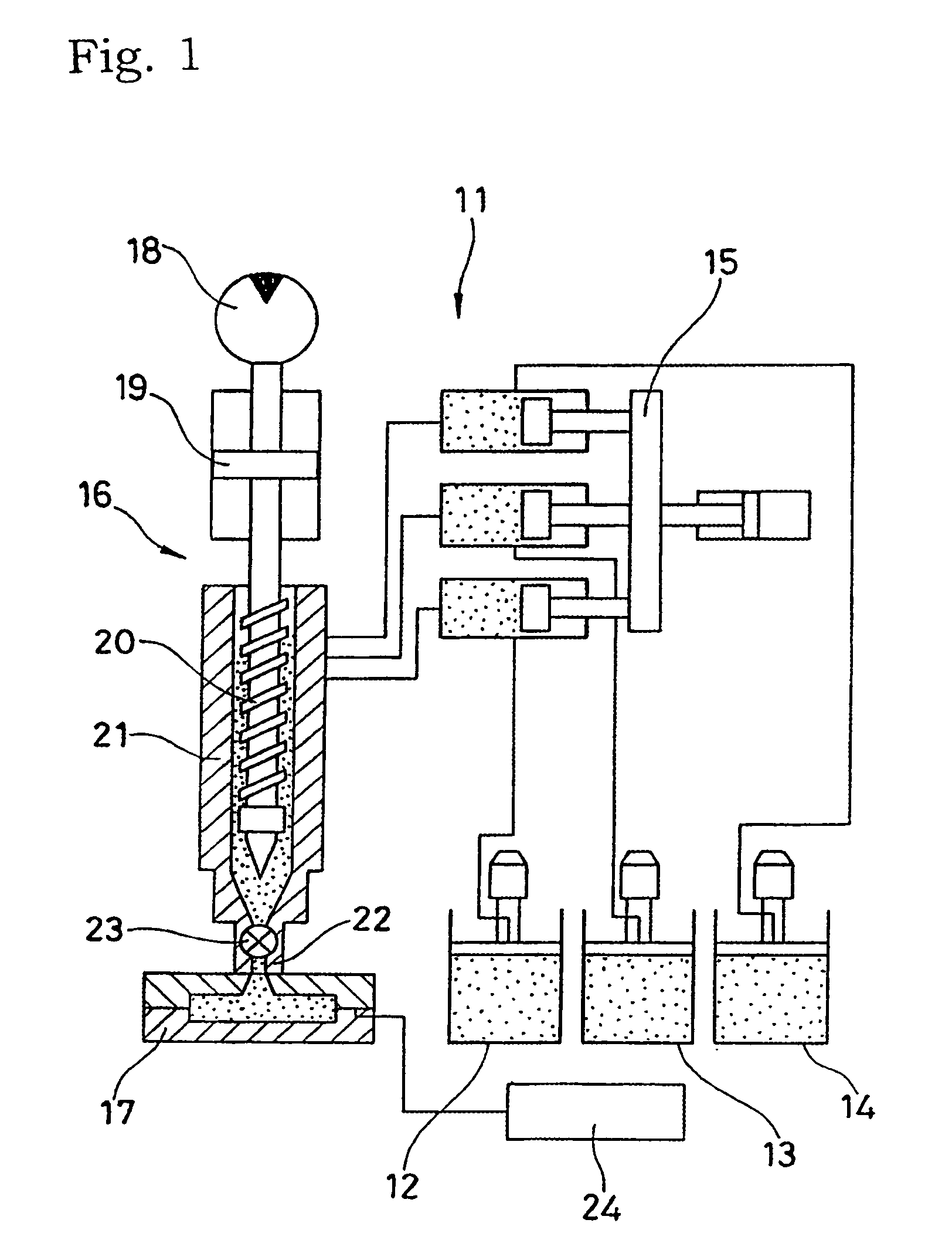
[0067]FIG. 1 shows a liquid injection molding apparatus 11 used for executing a method of forming a gasket in accordance with a first embodiment of the present invention. A gasket (also refer to a gasket lip or a gasket main body) is formed by injecting a molding material supplied from a base resin tank 12, a coloring agent tank 13 and a setting agent tank 14 to an injection apparatus 16 via a material supplying plunger 15, into a metal mold 17 from the injection apparatus 16. The injection apparatus 16 is provided with a screw 20 driven in accordance with an operation of a hydraulic motor 18 and an injection cylinder 19, and an injection cylinder 21 within which the screw 20 is inserted, and a shut-off valve 23 preventing an inflow of the molding material is arranged within a nozzle 22 at a front end of the injection cylinder 21 so as to be freely opened and closed. Further, an evacuation apparatus 24 constituted by a vacuum pump is connected to the metal mold 17.

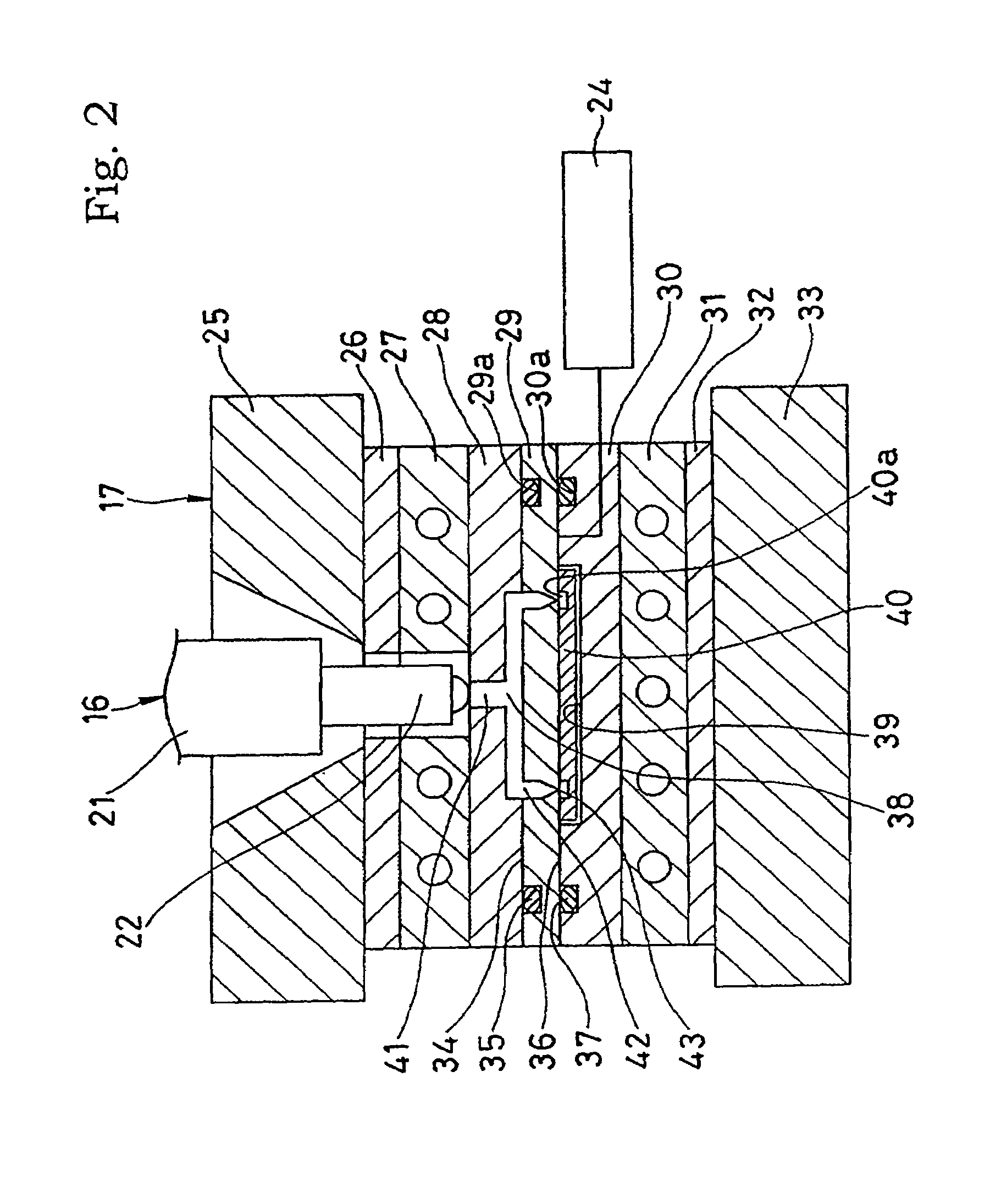
[0068]FIG. 2 shows...

second embodiment

[0074]In a second embodiment in accordance with the present invention shown in FIG. 4, groove portions 40a and 40b are formed so as to correspond to each other on an upper surface and a lower surface of a flat surface plate porous carbon member 40 previously placed in a cavity space 39, and as shown in FIG. 5A in an enlarged manner, the groove portions 40a and 40b are communicated with each other via a through hole (also referred as a communication hole) 40c open to a bottom surface of each of the groove portions 40a and 40b. The through hole 40 is structured, for example, a plurality of through holes having a diameter of 1 mm are formed at an interval between 10 and 20 mm.

[0075]Accordingly, when the molding material of the gasket is supplied to the carbon member 40, as shown in FIG. 5B, the gaskets 7 and 8 are integrally formed with both of the groove portions 40a and 40b via the through hole 40c simultaneously, whereby it is possible to realize making the seal portion thin, improv...

third embodiment

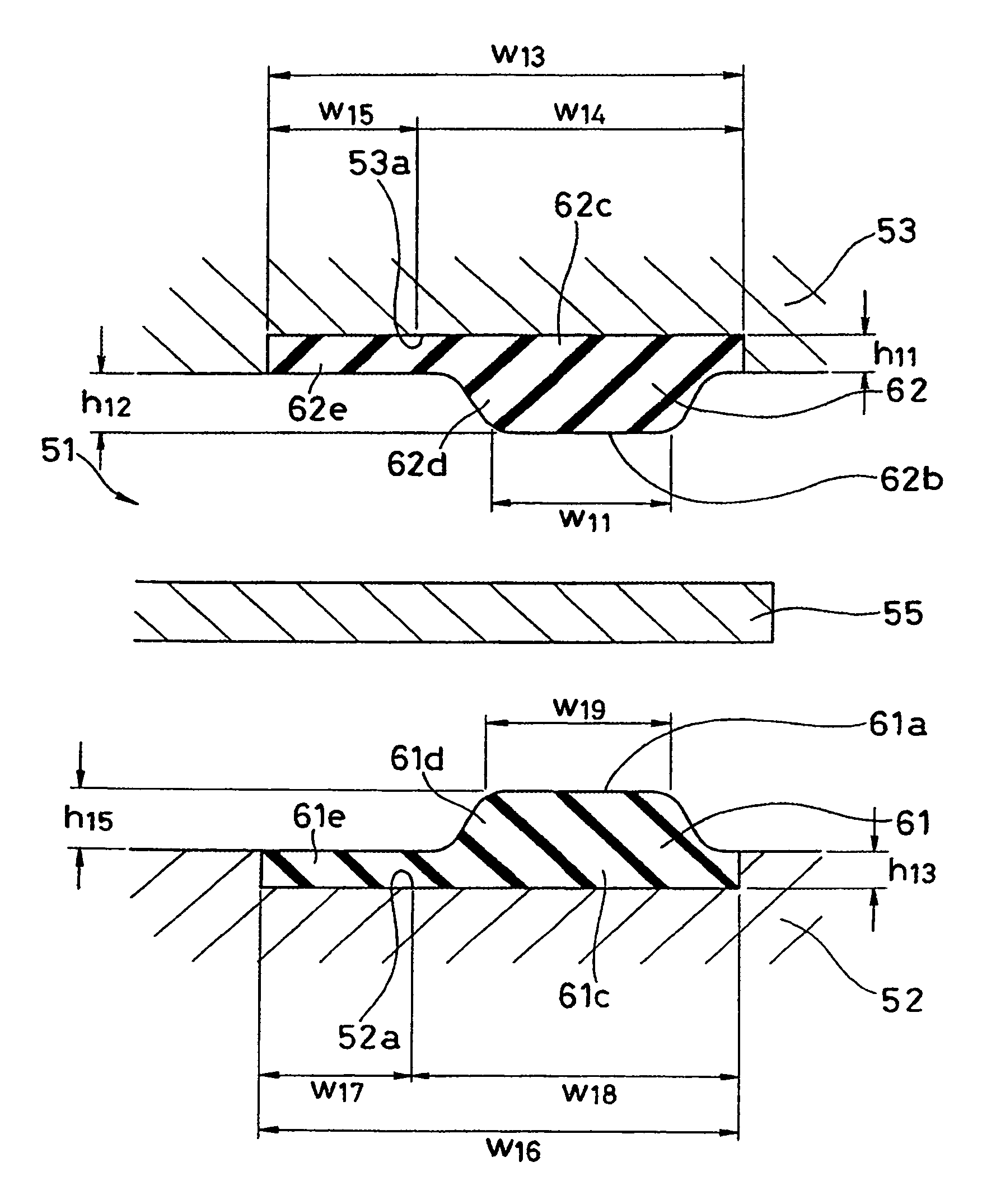
[0077]Next, FIG. 6 shows a cross section of a gasket for a fuel battery in accordance with a third embodiment of the present invention. This gasket is structure in the following manner.

[0078]That is, at first, an electrolyte membrane 55 is arranged between a pair of electrodes (also referred as outer electrodes) 52 and 53, and electrodes (also referred as inner electrodes) 59 and 60 are respectively arranged between the respective electrodes 52 and 53 and the electrolyte membrane 55, whereby a fuel battery cell 51 constituted by a five-layer laminated body made by arranging the electrode 52, the electrode 59, the electrolyte membrane 55, the electrode 60 and the electrode 53 mentioned above in this order is formed.

[0079]A pair of electrodes 52 and 53 respectively correspond to the collector electrodes (the separators) mentioned above, are formed by a carbon plate, with a thickness t1 of about 1 to 2 mm at actual size.

[0080]The electrolyte membrane 55 corresponds to the ion exchange ...


PUM

PropertyMeasurementUnit
heightaaaaaaaaaa
heightaaaaaaaaaa
viscosityaaaaaaaaaa

Abstract

In a gasket used for a fuel battery, in order to solve problems with respect to making a seal portion thin, improving an assembling property, preventing a position shift, making a surface pressure low, making the surface pressure uniform, and the like, a gasket lip made of a liquid rubber hardened material is integrally formed on a surface of a flat plate made of a carbon, a graphite, a conductive resin such as a conductive phenol resin or the like, an ion exchange resin, or a metal such as a stainless steel, a magnesium alloy or the like, or on a groove portion applied to the surface.

Description

[0001]This is a nationalization of PCT / JP00 / 03853, filed Jun. 14, 2000, and published in Japanese.TECHNICAL FIELD[0002]The present invention relates to a gasket for a fuel battery and a method of forming the same.BACKGROUND ART[0003]For example, as shown in FIG. 24, a fuel battery has flat plates such as collector electrodes (separators) 2, an ion exchange membrane 3 held between them, membrane fixing reaction electrodes 4 fixed to the ion exchange membrane 3 and the like, and these constituting elements are combined, whereby a fuel battery cell 1 is constituted. As a material of the flat plates, a graphite or the like is employed in addition to a carbon, and further, a conductive resin such as a conductive phenol, an ion exchange resin, a metal such as a stainless steel, a magnesium alloy or the like, and the like may be employed.[0004]With respect to a seal for the fuel battery cell 1 and a seal between the respective constituting elements, since a lot of seals are used for lamina...

Claims


Application Information

Patent Timeline
Patent Type & Authority Patents(United States)
IPC IPC(8): H01M8/02F16J15/16B29C45/14B29C45/34F16J15/00F16J15/10F16J15/14
CPCB29C45/14344F16J15/00F16J15/14H01M8/0271F16J15/108B29C45/34B29K2083/005Y02E60/50H01M2300/0082
Inventor NAGAI, OSAMUWAKAMATSU, SHIGEOKUROKI, YUICHI
Owner NOK CORP
Why Eureka
Try Eureka