
Analog base band unit for a RF receiver and method for using the same

a technology of analog base band unit and rf receiver, which is applied in the direction of gain control, transmission, amplifier, etc., can solve the problems of insufficient suppression of dc and low frequency components, automatic gain control methods used that do not compensate for changes in filter characteristics, and particularly severe problems of this typ

Active Publication Date: 2006-06-20
U-BLOX +1
View PDF29 Cites 16 Cited by
  • Summary
  • Abstract
  • Description
  • Claims
  • Application Information

AI Technical Summary

Benefits of technology

[0005]With appropriate modifications the analog base band unit can be adapted to various signal types implicating widely differing requirements, in particular frequency hopping systems like bluetooth requiring very fast responses on the one hand and TDMA, CDMA and GPS where response time requirements are more moderate but where, e.g., the intermittent character of the processed signal poses problems of a different type or where low power consumption requirements are particularly stringent. At the same time, the analog base band unit according to the invention offers efficient suppression of low frequency components, in particular DC offset.

Problems solved by technology

One particular problem associated with known designs is that the automatic gain control methods used do not compensate for changes in the filter characteristics of the system that go along with variations of the gain.
This may lead to shifts in cut-off frequencies resulting in insufficient suppression of DC and low frequency components resulting from local oscillator self-mixing or blocking self-mixing effects.
Problems of this type are particularly severe if signals of widely differing properties are to be processed by the receiver.

Method used


Image

  • Analog base band unit for a RF receiver and method for using the same
  • Analog base band unit for a RF receiver and method for using the same
  • Analog base band unit for a RF receiver and method for using the same

Examples


Embodiment Construction

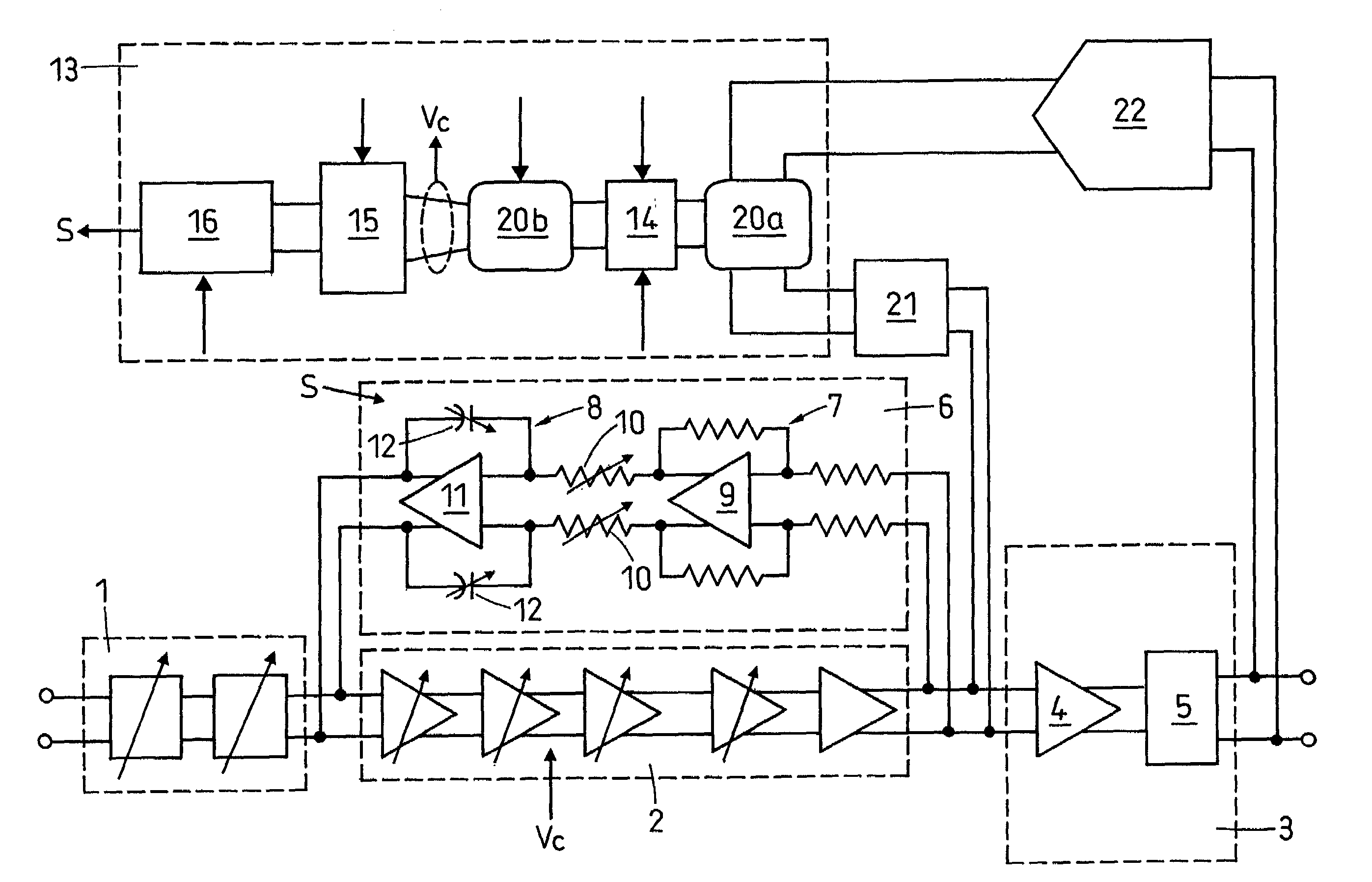
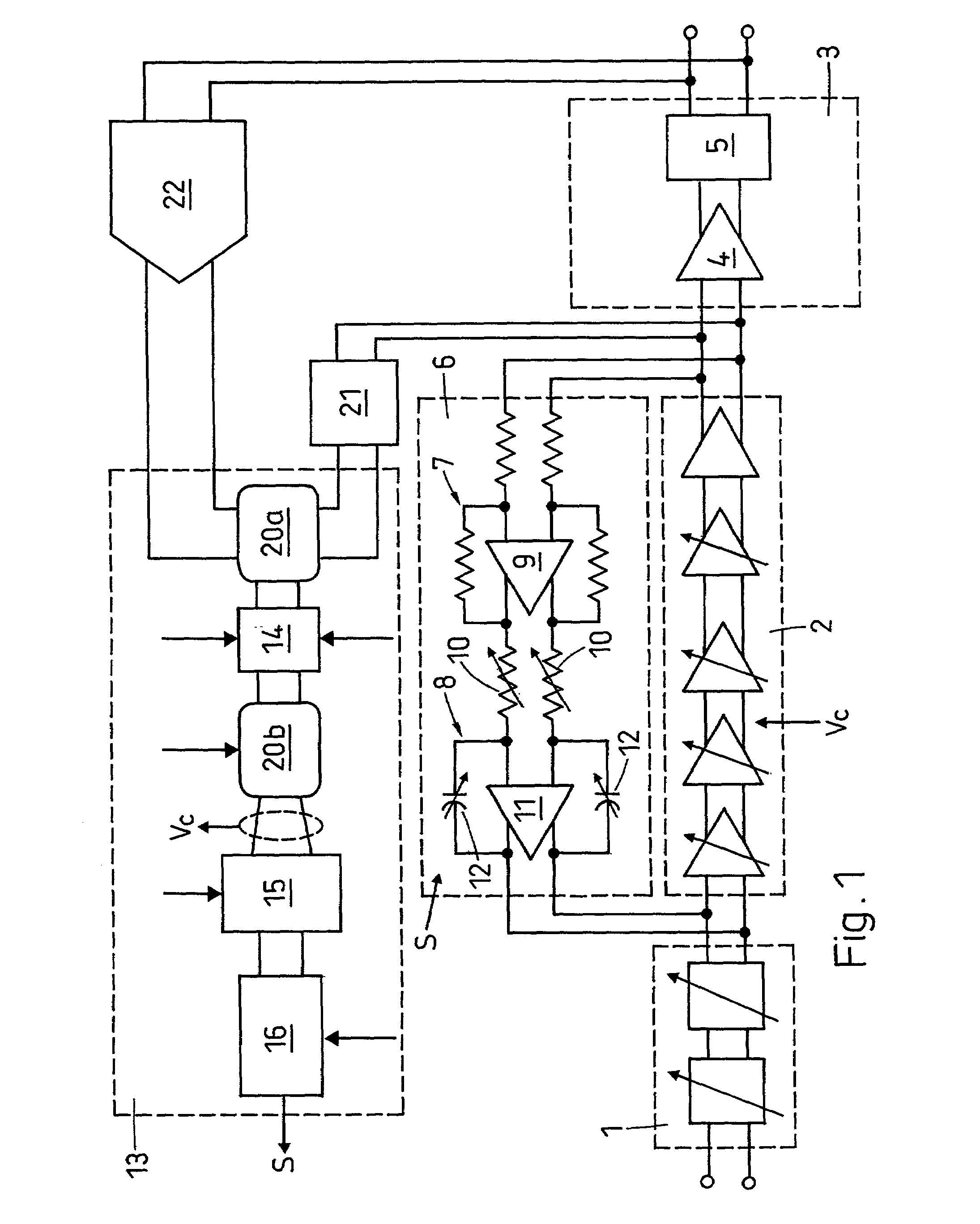
[0013]The analog base band unit of FIG. 1 is part of a RF receiver also comprising an analog front end and a digital base band unit as well as auxiliary components as is well known in the art. The input receiving the output signal of a mixer is directly connected to a cascaded low pass filter 1. Low pass filter 1 has variable properties, so it can be calibrated to provide compensation for component tolerances and adapted to the chosen mode of operation. Its output is connected to the input of a variable gain amplifier unit 2 in the shape of an amplifier chain made up of series connected amplifiers at least part of which are controllable with respect to gain. As controllable amplifiers Gilbert cells or amplification cells with operational amplifiers may be employed. This will ensure high gain and control range, low phase noise and coherent amplification as required. With Gilbert cells an analog control voltage Vc can be directly applied to control their gain whereas amplification cel...


PUM


Abstract

A feedback circuit for amplification of the output signal of an analog front end and suppression of its DC and low frequency components comprises a variable gain amplification unit (2) controlled by a gain control signal and a reverse path unit (6) comprising a filter unit (8) with variable time constant. A control unit (13) produces the gain control signal as well as a reverse path control signal (S) which causes adaptation of variable resistances (12) and capacitances (10) in such a way that the time constant of the filter unit (8) varies essentially proportionally with the gain of the variable amplifier unit (2). Thereby the gain of the feedback circuit as a function of the frequency retains its shape with varying gain. As the reverse path control signal (S) can be produced from different inputs selectable by selectors (20a, 20b) in the control unit (13) and due to the adaptability of the reverse path unit (6) and other features the analog base band unit is suited for the processing of signals of various types, e.g. signals pertaining to GPS and mobile telecommunication systems.

Description

FIELD OF THE INVENTION[0001]The invention concerns an analog base band unit for a RF receiver according to the precharacterizing clause of claim 1. Units of this type are used in receivers serving various purposes, in particular receivers used in wireless or TV sets, cellular phones or GPS kits. The invention also concerns a method for using the inventive analog base band unit to process a GPS signal.PRIOR ART[0002]Many analog base band units of the generic type are known. One particular problem associated with known designs is that the automatic gain control methods used do not compensate for changes in the filter characteristics of the system that go along with variations of the gain. This may lead to shifts in cut-off frequencies resulting in insufficient suppression of DC and low frequency components resulting from local oscillator self-mixing or blocking self-mixing effects. Problems of this type are particularly severe if signals of widely differing properties are to be proces...

Claims


Application Information

Patent Timeline
IPC IPC(8): H04B1/06H03G1/04H03G3/30
CPCH03G1/04H03G3/3052H03G3/30
Inventor SPIEGEL, SOLON
Owner U-BLOX
Learn More