Magnetic recording medium having a patterned soft magnetic layer

a soft magnetic layer and magnetic recording technology, applied in the field of patterned media, can solve the problems of reduced volume of switching unit (v) of each bit, loss of magnetized information, limited thermal fluctuation resistance, etc., and achieve the effect of low nois

Inactive Publication Date: 2006-06-27
KK TOSHIBA
View PDF20 Cites 94 Cited by
  • Summary
  • Abstract
  • Description
  • Claims
  • Application Information

AI Technical Summary

Benefits of technology

[0017]An object of the present invention is to provide a perpendicular magnetic recording type of patterned media low in noise and capable of writing / reading with a single magnetic pole head and a method for manufacture thereof.

Problems solved by technology

However, when the recording bit is made fine, the volume of switching unit (V) of each bit is reduced, involving a problem such that magnetization inversion due to thermal fluctuation causes loss of magnetized information.
However, as high density of a magnetic medium is further promoted from now on, the thermal fluctuation resistance becomes limited even with the perpendicular magnetic recording type.
As described above, because the patterned media can suppress the magnetization inversion due to the thermal fluctuation, it is effective as a high-density magnetic recording medium, but the manufacturing process is more complex than the other magnetic recording media.
Therefore, chemical etching using Reactive Ion Etching (RIE), etc., which is widely used in semiconductor processes, is difficult to be used, and thus, physical etching such as ion beam-milling is used instead.
However, because ions accelerated by an electric field are sputtered onto the sample surface, the ion beam-milling damages the processed surface.
This damage may cause noise during reproducing and recording.
Furthermore, there is a problem that manufacturing costs are great due to many process steps, and thus the development of a simpler manufacturing method is desired.
However, if the domain walls occur in the soft magnetic layer, they will cause noise during writing and reading.

Method used


Image

  • Magnetic recording medium having a patterned soft magnetic layer
  • Magnetic recording medium having a patterned soft magnetic layer
  • Magnetic recording medium having a patterned soft magnetic layer

Examples


first embodiment

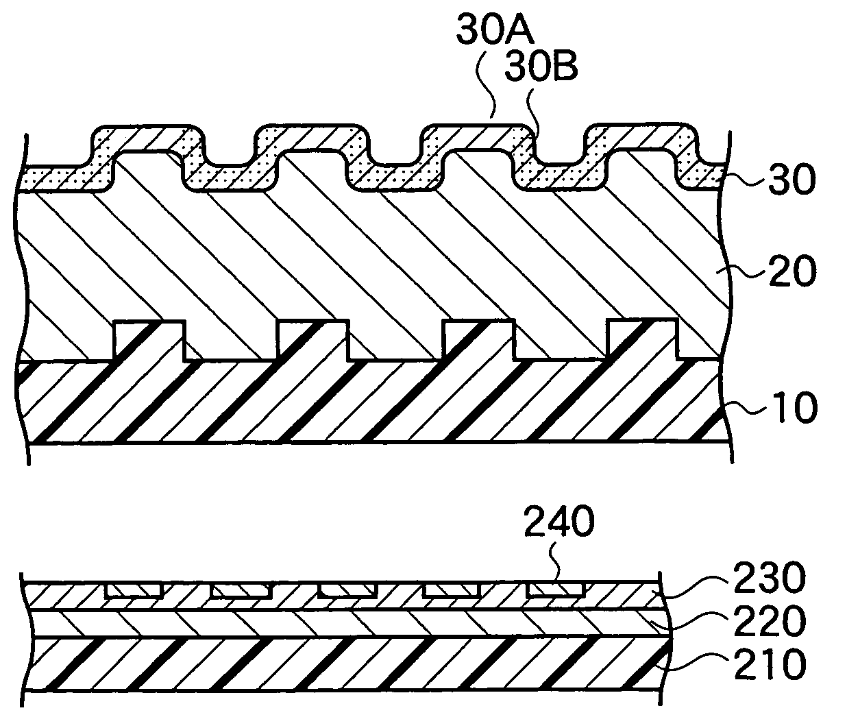
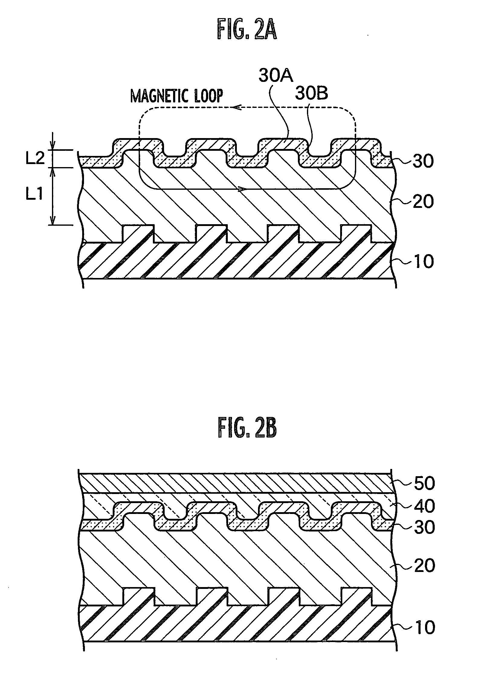
[0034]A first embodiment relates to a magnetic recording medium and a method for manufacture thereof. In the magnetic recording medium, a soft magnetic layer and a ferromagnetic layer of perpendicular magnetic anisotropy are serially laminated on a non-magnetic substrate having a plurality of projected parts arranged regularly and recessed parts surrounding each projected part on the surface thereof, in which the substrate is made by an injection molding method. According to the structure of this magnetic recording medium, projected parts and recessed parts reflecting the shape of the non-magnetic substrate are formed also on the soft magnetic layer and the ferromagnetic layer, and the so-called patterned media in which the projected parts of the ferromagnetic layer are specified only as recording areas.

[0035]Note that in the present invention, the ferromagnetic layer means a layer capable of having ferromagnetism according to the state of the laminated structure, etc., and the soft...

example 1

[0066]First, a cylindrical non-magnetic substrate 10 provided with projected parts and recessed parts was formed by an injection molding. A mold used for the injection molding was the one having a plurality of rectangular projected parts arranged regularly on the surface as shown in FIG. 3A. This injection molding mold was formed by patterning a barrel-shaped cylinder by using an EB exposure method to obtain the mold thereof by Ni-electroforming. The upper surface of the rectangular projected part was set to 50 nm, and the height of the recesses and projections was set to 50 nm.

[0067]Specifically, polycarbonate material was prepared as the non-magnetic substrate, and poured to a hopper of an injection molding machine. Then, injection molding was performed under conditions of the temperature of the mold at 125° C., the temperature of resin at 340° C., injection pressure at 30 t, and cycle time at 12 seconds. In this way, a barrel-shaped polycarbonate cylinder with a size of 200 nm in...

example 2

[0072]In example 2, a non-magnetic substrate was formed by an injection molding method using a mold having fine pattern formed thereon by use of the self-organizing function of di-block polymer. Other than the non-magnetic substrate, a magnetic recording medium was formed under the same conditions as in example 1.

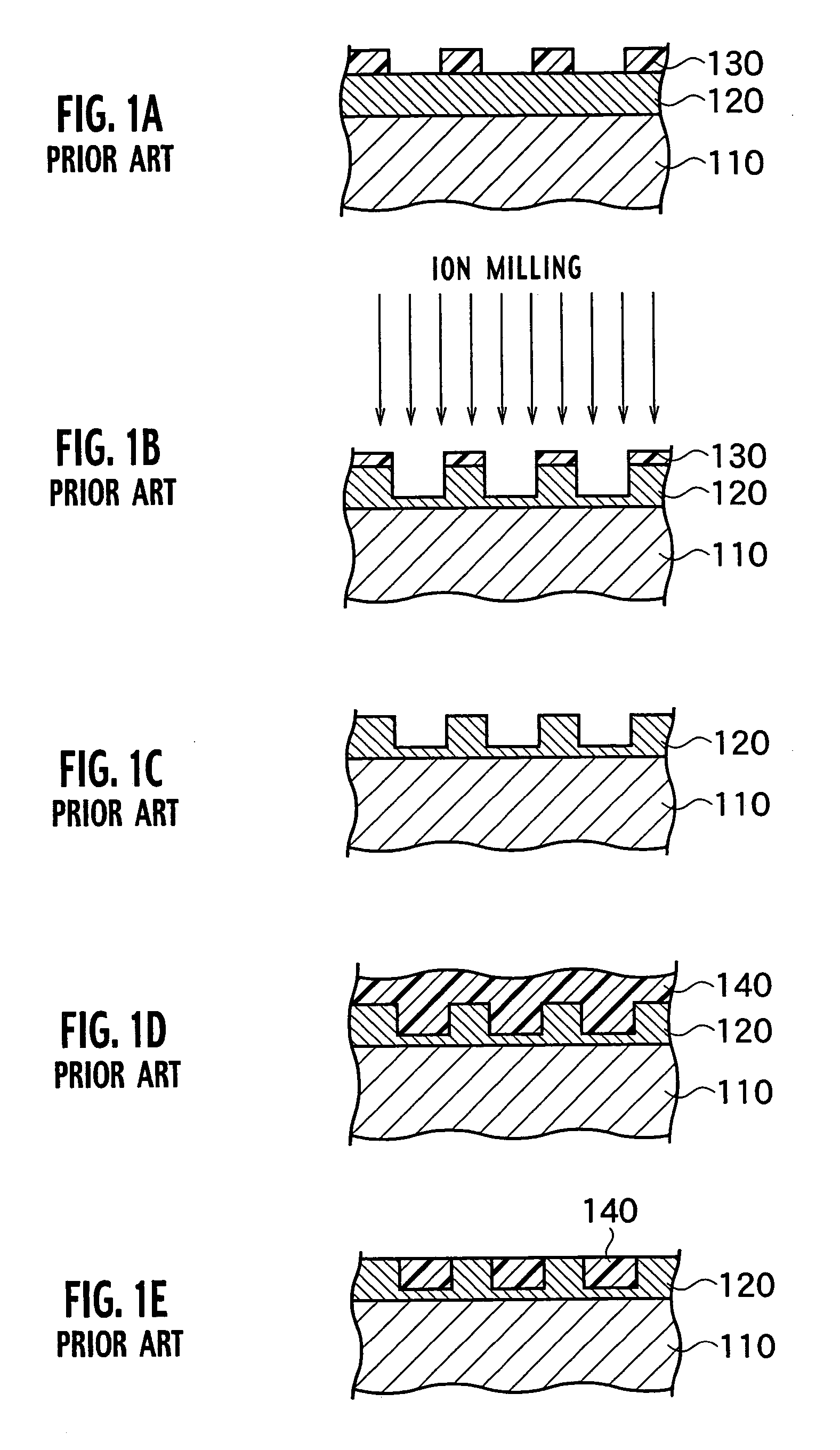
[0073]That is, a liquid agent mixed with PS-PMMA di-block copolymer (PS: polystyrene; PMMA: poly-methyl-methacrylate) was coated over a barrel-shaped cylinder to obtain a sea-islands structure in which island-like regions made of PMMA and a sea-like region made of PS are separated in a phase. These regions are exposed to ozone to vaporize PS selectively, to obtain a regular dot pattern of PMMA. Thereafter, ion-milling was performed using the dot pattern of PMMA as a mask; Ni is coated by sputtering over the surface of the barrel-shaped cylinder having recesses / projections formed thereon by etching; a conduction treatment is carried out thereon; and further an injection mold...


PUM

PropertyMeasurementUnit
thicknessaaaaaaaaaa
thicknessaaaaaaaaaa
thicknessaaaaaaaaaa

Abstract

A magnetic recording medium includes a non-magnetic substrate; a soft magnetic layer which is formed on the non-magnetic substrate and which includes projected parts arranged on the surface thereof and recessed parts surrounding each of the projected part; and a ferromagnetic layer which is formed on the soft magnetic layer and which includes projected parts and recessed parts reflecting the projected parts and the recessed parts of the soft magnetic layer. Further the magnetic recording medium includes recording areas which have perpendicular magnetic anisotropy and ferromagnetism, and which are formed of the projected parts of the ferromagnetic layer and separated magnetically from their surroundings. A method for manufacture of the magnetic recording medium includes forming a soft magnetic layer including of projected parts arranged regularly on the surface thereof and recessed parts surrounding each projected part; and forming a ferromagnetic layer having perpendicular magnetic anisotropy on the soft magnetic layer.

Description

CROSS REFERENCE TO RELATED APPLICATIONS[0001]This application is based upon and claims the benefit of priority from prior Japanese Patent Application No. 2002-326057, filed on Nov. 8, 2002; the entire contents of which are incorporated herein by reference.BACKGROUND OF THE INVENTION[0002]1. Field of the Invention[0003]The present invention relates to a high density magnetic recording technology and particularly to a patterned media capable of high density perpendicular magnetic recording and a method for manufacture thereof.[0004]2. Description of the Related Art[0005]In recent years, with the progress of multimedia application of data such as pictures, images, and voice, and an amount of information data for searching per user has increased. Therefore, a larger capacity and higher speed of database are required. Meanwhile, due to improvement in the surface recording densities of magnetic recording media associated with increases in the recording capacity of Hard Disk Drives (HDDs),...

Claims


Application Information

Patent Timeline
Patent Type & Authority Patents(United States)
IPC IPC(8): G11B5/667G11B5/73G11B5/65G11B5/84G11B5/855
CPCB82Y10/00G11B5/855G11B5/743G11B5/667
Inventor KAMATA, YOSHIYUKISAKURAI, MASATOSHIKIKITSU, AKIRA
Owner KK TOSHIBA
Why Eureka
Try Eureka