
Systems for generating high-power short-pulse laser light

Inactive Publication Date: 2006-07-04
JAPAN ATOM ENERGY RES INST
View PDF9 Cites 10 Cited by
  • Summary
  • Abstract
  • Description
  • Claims
  • Application Information

AI Technical Summary

Benefits of technology

[0040]c) Introducing seed pulses by the half-waist reflection method and the tandem crystal method for the purpose of reducing the simulated Raman scattering effect.
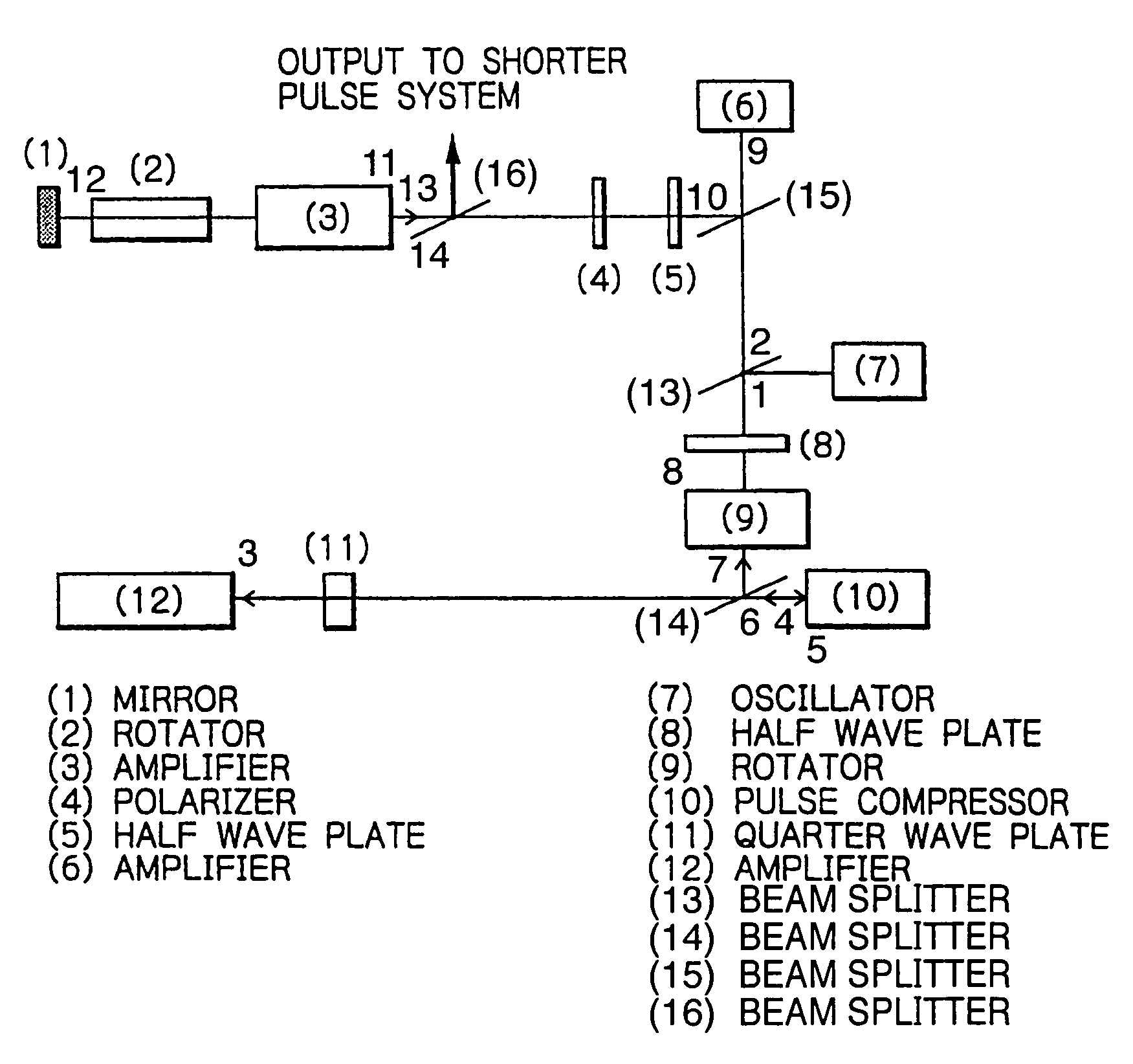
[0047]In the generator, the pumped laser light from the oscillator is introduced into a preamplifier and amplified; the amplified light is introduced into the SBS pulse compressor and the resulting short-pulse laser light is introduced into the same preamplifier and amplified; the amplified laser light is introduced into another preamplifier, amplified and further amplified in a master amplifier, thereby producing amplified laser light having a shorter pulse duration.

Problems solved by technology

The development of these techniques requires optical data for nonlinear crystals but none of them have been available.

Method used


Image

  • Systems for generating high-power short-pulse laser light
  • Systems for generating high-power short-pulse laser light
  • Systems for generating high-power short-pulse laser light

Examples


example 1

Acquisition of Optical Data for the Compression of SBS Pulses

[0083]SBS compression was performed with two cells used to prevent SRS. The gain of two passes as calculated from the amplification characteristics for two passes was 2.3. As shown in the graph on the right side of FIG. 7, the pulse duration as obtained when the condensing optics in the above-described pump laser configuration had a focal length of f-15 mm was 320 ps in terms of FWHM.

example 2

Acquisition of Optical Data for Raman Amplification and Compression

[0084]The threshold for SRS with Ba(NO3)2 was measured by the beam waist reflection method using a setup of the layout shown in FIG. 8, with a mirror placed at the half beam waist. With varying values of excitation intensity, gain g was determined to be g˜10 cm / GW with crystal length of 300 mm. Based on this data, compressing pump pulses of about 100 ps was assumed and the laser beam was so issued as to have a half waist at the reflecting face (exit end) of the crystal. Channeling due to self-focusing might damage the reflective coating at the exit face of the crystal and the expected intensity of the damage is about 2–2.5 GW / cm2 for the given value of pulse duration.

[0085]Optical design must therefore be made to provide values not exceeding the calculated damage intensity. The threshold for SRS with Ba(NO3)2 given such design values was about 30 kW. The multiplication factor was M˜40. The cross-sectional area of the...

example 3

Producing Shorter Pulses with Laser System

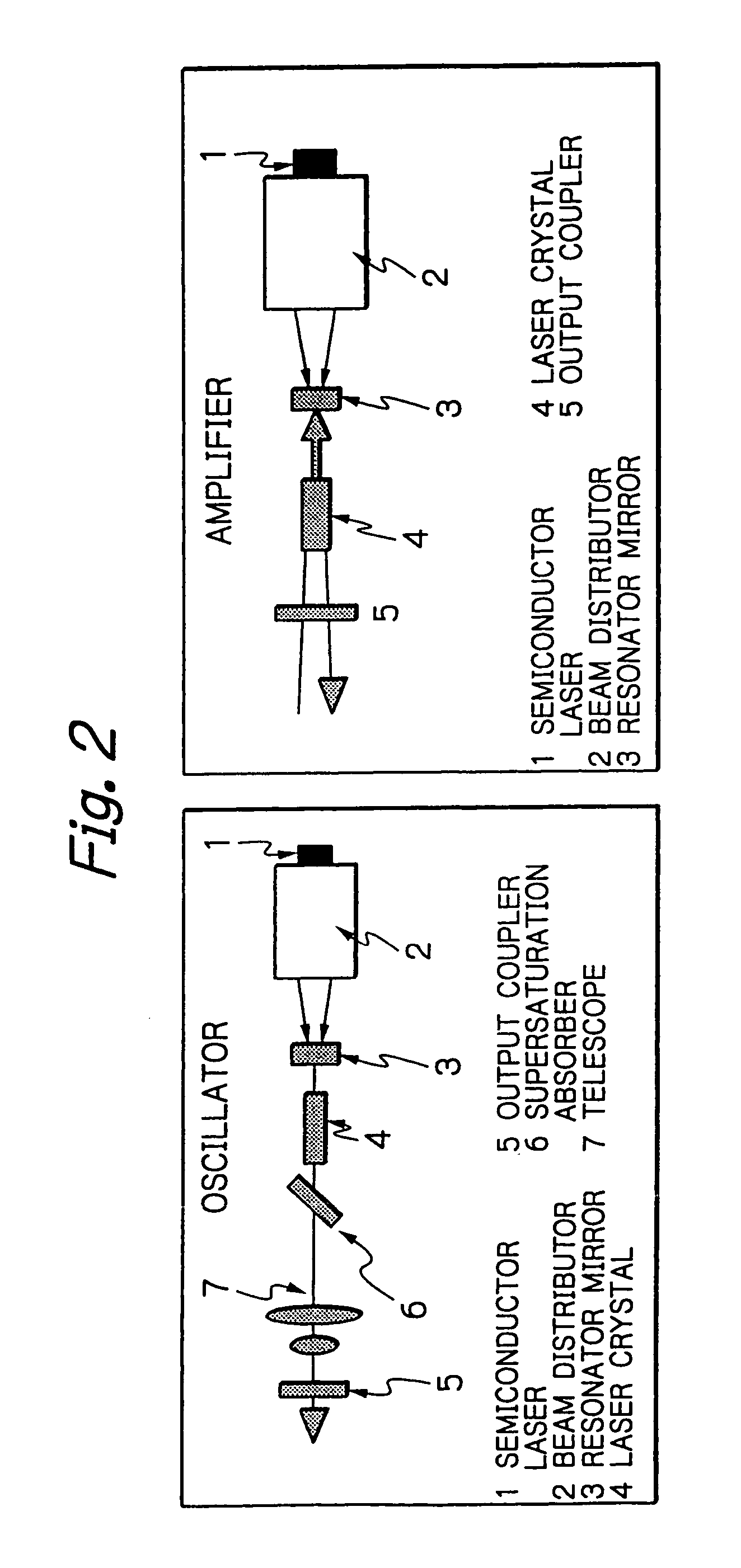
[0090]In a semiconductor pumped by all-solid Nd:YAG laser oscillator, a Cr:YAG crystal was inserted as a supersaturation absorber and by pumping with a 100 W, 300 μs semiconductor laser, 600 μJ laser light was produced as a sequence of 3 ns pulses. This light was amplified with a first preamplifier and compressed to a pulse duration of about 0.3 ns in a SBS pulse compressor. The compressed pulses were fed into the first preamplifier and amplified to an energy of 1.5 mJ in the form of 0.35 ns pulses. The light was further amplified in a second preamplifier to a pulse energy of 6 mJ in the form of 0.32 ns pulses. Finally, the light was subjected to 4-pass amplification in a master amplifier which was a 1200 W semiconductor laser (120 A, 300 μs, 100 Hz), thereby producing 32 mJ short-pulse pump light having a pulse duration of 0.3 ns.

[0091]The short-pulse pump laser light (λ=1061 nm) was introduced into a Raman amplifier / compressor comprising a...


PUM


Abstract

A method for generating ultra-short pulse amplified Raman laser light. Short pulse laser light is amplified, and a portion thereof is introduced into a Raman oscillator to produce compressed laser light. The compressed light is introduced to a first Raman amplifier. The remainder of the short pulse laser light is introduced to a polarizer, and the reflected light is introduced into the first Raman amplifier to pump it. The light transmitted through the first Raman amplifier that has not contributed to pumping is introduced to a beam splitter to produce a second reflected light that is passed to a second Raman amplifier to pump that amplifier. The compressed light is amplified in the first Raman amplifier and introduced to the second Raman amplifier to further amplify it. This further amplified radiation is passed through delay lines to the beam splitter, which passes only first Stokes radiation to generate ultra-short pulse amplified Raman laser light.

Description

[0001]This application is a continuation of U.S. application Ser. No. 09 / 903,732, filed Jul. 13, 2001 now U.S. Pat. No. 6,751,240, the entirety of which is hereby incorporated by reference, and foreign priority of Japan application no. 213587 / 2000 filed Jul. 14, 2001.BACKGROUND OF THE INVENTION[0002]This invention relates to the fabrication of the lasers described below, as well as their use in various applications including micromachining, analyses by high-intensity short-pulse x-rays and medical diagnoses and treatments.(1) Fabrication of Industrially Applicable Short-Pulse High-Peak Power Lasers[0003]Short-pulse high-peak power lasers have a history of more than 10 years on the commercial market and yet they have not been used at industrial sites. FIG. 10A shows a conventional laser system constructed by incorporating a Ti:sapphire laser into the CPA (chirped pulse amplification) technology; as shown, the system consists of a mode-locked laser (and a pump laser), a diffraction gr...

Claims


Application Information

Patent Timeline
IPC IPC(8): H01S3/30H01S3/10B41J2/44A61B18/20A61C3/02A61N5/06A61N5/10G02F1/35H01S3/00H01S3/109H01S3/23
CPCH01S3/30H01S3/0057H01S3/09415H01S3/10092H01S3/113H01S3/2308H01S3/2333H01S3/109
Inventor ARISAWA, TAKASHIDEKI, KYOICHIMATSUOKA, FUMIAKI
Owner JAPAN ATOM ENERGY RES INST
Learn More