
Combination power and full duplex data cable

Inactive Publication Date: 2006-07-04
RATEZE REMOTE MGMT LLC
View PDF50 Cites 48 Cited by
  • Summary
  • Abstract
  • Description
  • Claims
  • Application Information

AI Technical Summary

Benefits of technology

[0016]The present invention integrates power distribution throughout the coaxial cables of a NAN to remote sites. The shield of one coaxial cable may be the positive polarity and the shield of a second coaxial cable may be the negative polarity of the NAN power system. Due to the relatively low resistance of shielding and the use of high voltage switching regulators, system power may be distributed over a 4,000 foot segment of coaxial cable. Power distribution in the shields further reduces noise input into the center conductor and improves signal to noise ratios for data transmission. The capability of providing 4,000 foot long NAN distribution segments permits convenient and economical installation of distribution boxes at central locations for connection to AC line power taps, as well as, uplinks to the NAN servers.
[0017]A coaxial cable may be placed in electrical communication with a converter to convert the coaxial data to differential data. The differential data is then transmitted to a local Cat-5 cable that is in communication with a local destination. The converter further receives differential data from the Cat-5 cable, converts it to coaxial data, and transmits the coaxial data to the coaxial cable. In one embodiment, the converter may further include an amplifier to boost the coaxial data into the coaxial cable. Such boosting overcomes the attenuation caused by the comparatively longer transmission distances. The converter further receives and transmits system power between the coaxial cable and the power bus. System power may be directed across the Cat-5 cable to power local devices at a destination in the network. System power may also be directed from the converter to power other network devices in communication with the converter, such as a switch. The NAN system may employ a switch in communication with the converter to route data and system power to one of a plurality of coax cables to arrive at a specific destination.
[0018]The present invention provides a system to integrate power and data into a typical NAN. The present invention extends the distance of individual data segments between switches, pedestals and aerial boxes, beyond the industry-specified maximums. The NAN system of the present invention extends the range for power distribution such that the NAN system requires at least ten (10) times fewer power taps from power utilities. The NAN system provides increased reliability and economy of data and power distribution cables. The NAN system further converts Cat-5 differential data signals to single ended coaxial cable signals to thereby extend range and to take advantage of the hardy coaxial cable reliability.

Problems solved by technology

Fiber transceiver nodes are also more expensive than for UTP, such as Cat-5.
Fiber cable is also limited in that it is a dielectric material and cannot conduct electrical power.
Thus, fiber cable cannot be used to supply electric power to remote sites.
The amount of power that can be so transferred is limited by the resistance of the Cat-5 wire, which may be approximately 9–10 ohms per 100 meters.
The amount of transferable power is also limited by the dielectric and electrical code limitations on voltage range.
However, this technique is impractical for longer distances because of the degradation of the signal to noise ratio.
Such degradation is caused by increased noise generated by power supply current through greater lengths of cable in addition to the decreased signal level.
Another disadvantage of this technique is the high cost of quality inductors.
The relatively expensive inductors are required to isolate signals from power without seriously altering the delicate IEEE 802.32u specification for 100Base-TX signals.
The disadvantage of the first method is the relatively high cost and quality of the chokes and filters required to effectively separate the power from the RF in the face of power system noise and transients.
However, conventional specifications do not support the use of coaxial cable in a NAN.

Method used


Image

  • Combination power and full duplex data cable
  • Combination power and full duplex data cable
  • Combination power and full duplex data cable

Examples


Embodiment Construction

[0029]The presently preferred embodiments of the present invention will be best understood by reference to FIGS. 1–8, wherein like parts are designated by like numerals throughout. It will be readily understood that the components of the present invention, as generally described and illustrated in the figures herein, could be arranged and designed in a wide variety of different configurations. Thus, the following more detailed description of the embodiments of the apparatus, system, and method of the present invention, as represented in FIGS. 1 through 8, is not intended to limit the scope of the invention, as claimed, but is merely representative of presently preferred embodiments of the invention.

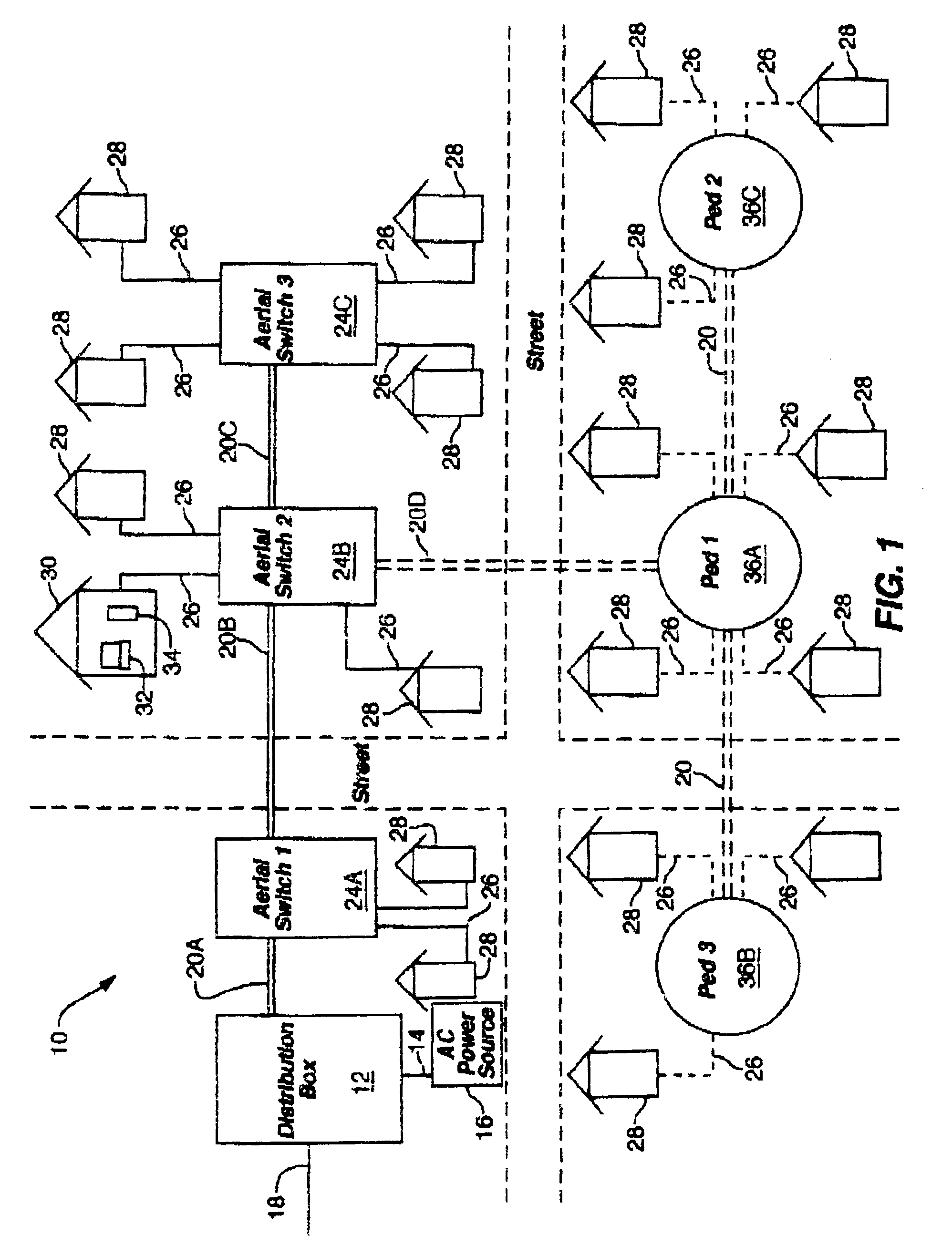
[0030]Referring to FIG. 1, a diagram of one embodiment of a NAN 10 of the present invention is shown. The NAN 10 is configured to distribute both data and power throughout its various segments. The NAN 10 includes a distribution box 12 which may be in electrical communication with a power...


PUM


Abstract

Systems, methods, and devices related to data converters are provided. In one particular embodiment, a network system data converter is provided. The network system data converter can include a first port that connects to a first cable for receiving data transmitted in a first signal transmission type, circuitry arranged and configured to convert the data from the first signal transmission type to a second signal transmission type and to transmit the converted data and power within the network system and, a second port that connects to a second cable for transmitting the data in the second signal transmission type and the power to a data device in the networks system. In one particular embodiment, the first signal transmission type can be differential data transmission and the second signal transmission type can be coaxial data transmission.

Description

RELATED APPLICATIONS[0001]This application claims priority to U.S. Pat. application Ser. No. 60 / 179,060 filed Jan. 31, 2000.BACKGROUND OF THE INVENTION[0002]1. Field of the Invention[0003]The present invention relates to the field of Neighborhood Area Networks (NANs), and more specifically to NANs incorporating coaxial cable to increase the data rate and distance of the NAN.[0004]2. Description of the Related Art[0005]Local area networks (LANs), including ATM, Frame Relay, and Token Ring, are very successful in providing data communication and are used throughout the industry. Numerous LANs use the Ethernet standards set forth by the IEEE 802.3. Under this standard, 100Base-TX (100 Mbit) baseband data signals are transferred over unshielded twisted pairs (UTP) such as Cat-5. Under Ethernet standards, transmission distances are limited to the IEEE 802.3-specified 100 meter maximum. The 100 meter maximum is based upon CSMA / CD collision domain and Cat-5 attenuation criteria. When signi...

Claims


Application Information

Patent Timeline
IPC IPC(8): H04B3/00H04L25/00H04B3/54
CPCH04B3/542H04B3/548H04B2203/5425H04B2203/5491H04B2203/547H04B2203/5483H04B2203/5445
Inventor SCHURIG, ALMA K.
Owner RATEZE REMOTE MGMT LLC
Features
  • Generate Ideas
  • Intellectual Property
  • Life Sciences
  • Materials
  • Tech Scout
  • Unparalleled Data Quality
  • Higher Quality Content
  • 60% Fewer Hallucinations
Learn More