Slot antenna

a slot antenna and antenna technology, applied in the direction of slot antennas, antenna feed intermediates, antennas, etc., can solve the problems of low power characteristics, low power characteristics of these types of antennas, and inability to meet the needs of small antennas, etc., to achieve low power, low power, and low power characteristics

Inactive Publication Date: 2006-07-11
RGT UNIV OF MICHIGAN
View PDF18 Cites 23 Cited by
  • Summary
  • Abstract
  • Description
  • Claims
  • Application Information

AI Technical Summary

Problems solved by technology

Whereas significant efforts have been devoted towards achieving low power and miniaturized electronic and RF components, issues related to design and fabrication of efficient, miniaturized, and easily integrable antennas have been overlooked.
The early studies of small antennas were restricted to the establishment of fundamental limitations of these types of antennas with regard to the antenna size and bandwidth.
Most successful designs, however, rely on the use of high permittivity ceramics, which are not suitable for monolithic integration.
Since there are neither polarization nor mismatch losses, the antenna efficiency is limited only by the dielectric and Ohmic losses of the substrate on which the antenna is made.
However, creating a physical open circuit for slot lines is not practical.

Method used


Image

  • Slot antenna
  • Slot antenna
  • Slot antenna

Examples


example i

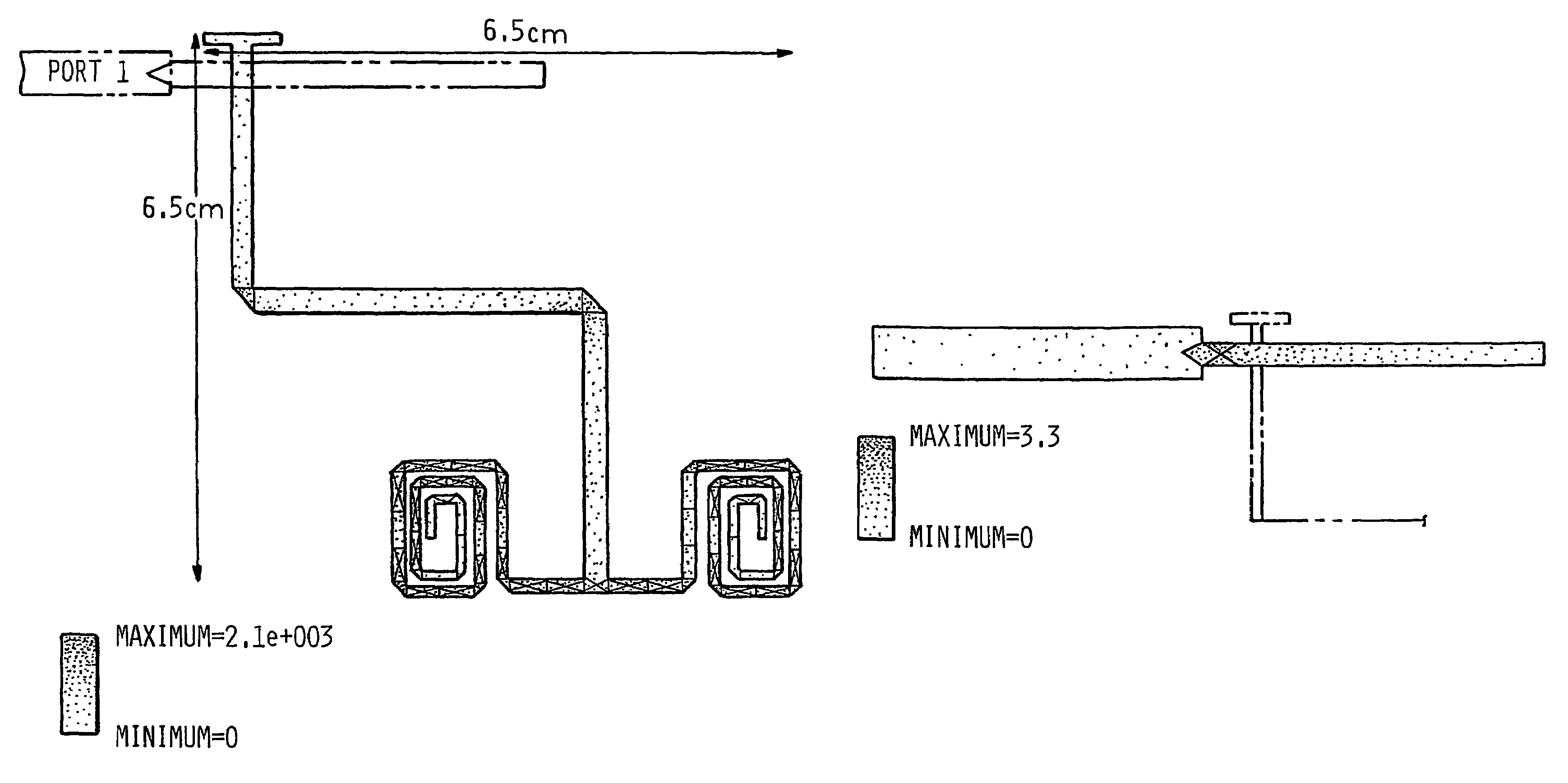
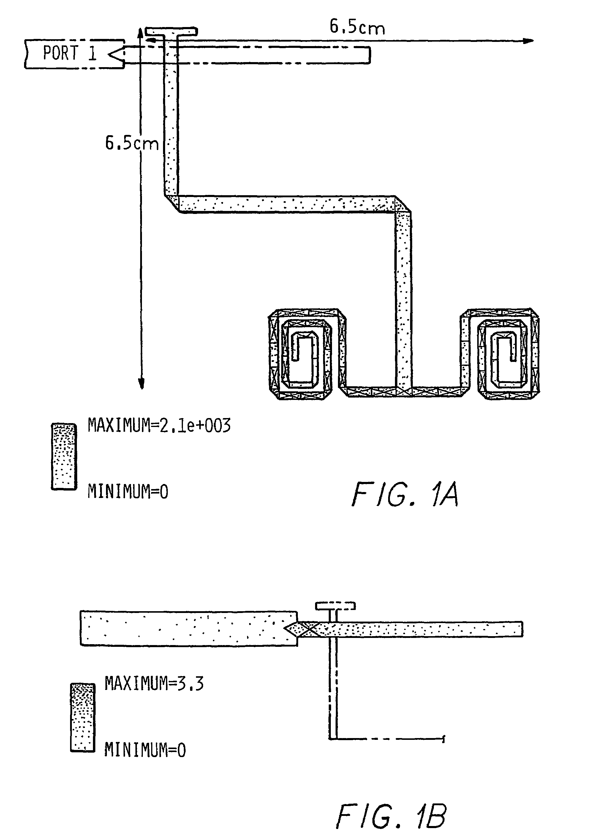
[0047]FIGS. 1A and 1B respectively, show the electric current distribution on the microstrip feed and the magnetic current distribution on the slot of the compact UHF antenna designed to operate at 600 MHZ. An ordinary FR4 substrate with thickness of 3 mm (120 mil.) and dielectric constant ∈r=4. PiCASSO™ software was used for the simulations of this antenna. The microstrip feed is constructed from two sections: 1) a 50Ω line section, and 2) an open-ended 80Ω line. The 80Ω line is thinner which allows for compact and localized feeding of the slot. The length of this line is adjusted to compensate for the reactive component of the slot input impedance. Noting that the slot appears as a series load in the microstrip transmission line, a line length of less than λm / 4 compensates for an inductive reactance and a line length of longer than λm / 4 compensates for a capacitive reactance. Here λm is the guided wavelength on the microstrip line. First a quarter wavelength section was chosen for...

example ii

[0051]An antenna based on the layout shown in FIGS. 1A and 1B was made on a FR4 printed-circuit-board. In the first realization, the size of the ground plane was chosen to be 8.5 cm×11 cm. The return loss of this antenna was measured with a network analyzer and the result is shown by the solid line in FIG. 4. It is noticed that the resonant frequency of this antenna is at 568 MHz, which is significantly lower than what was predicted by the simulation. Also the measured return loss for the designed microstrip feed line was around −10 dB. To get a better return loss the length of the microstrip line had to be extended slightly. FIG. 4 shows the measured return loss after the modification. The gain of this antenna was also measured against a calibrated antenna. Under a polarization matched condition a gain of −5.0 dBi (gain in dB against an isotropic radiator) is measured. The simulated gain value of this antenna using an infinite ground plane and ∈=4.0 is found to be 2.8 dBi. The diff...

example iii

[0087]In this section, simulation results for the antenna according to the present invention are illustrated. FIG. 17 shows the antenna geometry matched to a 50Ω line. As seen in FIG. 17 and suggested by Table 5, the feed line has been extended a short distance beyond the slot line. The width of the microstrip where it crosses the slot is reduced so that it may block a smaller portion of the radiating slot. It is worth mentioning that the effect of the feed line width on its coupling to the slot was investigated, and it was found that as long as the line width is much smaller than the radiating slot length, the equivalent circuit parameters do not change considerably.

[0088]As mentioned, the antenna has been simulated using a commercial software (IE3D). Using this software, the return loss (S11) of the antenna is calculated and shown in FIG. 16. In order to experimentally validate the design procedure, equivalent circuit model and simulation results, the antenna was fabricated on a 0...


PUM


Abstract

The present invention disclosed design aspects and the measured results of a miniaturized resonant narrow slot antenna. The resonant narrow slot radiating elements have a planar geometry and are capable of transmitting vertical polarization when placed nearly horizontal. A resonant narrow slot antenna according to the present invention simplifies impedance matching. Slot dipoles can be excited by a microstrip line and can be matched to arbitrary line impedances by moving the feed point along the slot. Antenna miniaturization can be achieved by using a high permittivity or permeability substrate and superstrate materials and / or using an appropriate antenna topology. Miniaturization is achieved through providing a unique geometry for a resonant narrow slot antenna. A very efficient radiating element is provided. With the virtual enforcement of the required boundary condition at the end of a slot antenna, the area occupied by the resonant antenna can be reduced. To achieve the required virtual boundary conditions, the two short-circuit at the end of resonant slot are replaced by some reactive boundary conditions, including inductive or capacitive boundary conditions, including inductive or capacitive loadings.

Description

STATEMENT REGARDING FEDERALLY SPONSORED RESEARCH OR DEVELOPMENT[0001]The U.S. Government may have a paid-up license in this invention and the right in limited circumstances to require the patent owner to license others on reasonable terms as provided for by the contract No. DAAD 19-99-1-0197 by the U.S. Army Research Office.FIELD OF THE INVENTION[0002]The present invention relates to efficient miniaturized resonant slot antennas, and more particularly to loaded resonant slot antennas, or folded resonant narrow slot antennas.BACKGROUND OF THE INVENTION[0003]The topic of small antennas has been of prolonged interest and goes back more than half a century. Using the area of the substrate more effectively in microwave circuits, as part of a general trend in monolithic circuit integration and antenna invisibility for certain applications, has been among the major motivations. On the other hand, in the radio communication, where the line of sight communication is not generally possible, t...

Claims


Application Information

Patent Timeline
Patent Type & Authority Patents(United States)
IPC IPC(8): H01Q13/10
CPCH01Q13/10
Inventor AZADEGAN, REZASARABANDI, KAMAL
Owner RGT UNIV OF MICHIGAN
Why Eureka
Try Eureka