
Fire and corrosion resistant thermally stable electrodes and batteries and method for manufacturing same

a thermal stable, electrode technology, applied in the direction of cell components, sustainable manufacturing/processing, flat cell grouping, etc., can solve the problems of degrading the communication of electrical current from the adjacent active material of the electrode, shards posing a constant danger of damage to the separator, aluminum and copper are especially susceptible to corrosion, etc., to achieve a wide range of corrosion potential, minimize corrosion, and maximize conductivity

Inactive Publication Date: 2006-07-18
GP BATTERIES INT LTD
View PDF16 Cites 0 Cited by
  • Summary
  • Abstract
  • Description
  • Claims
  • Application Information

AI Technical Summary

Benefits of technology

[0016]The above problems, and others are overcome by the herein disclosed components and method of construction of an improved Lithium and lithium ion battery. The device features current collectors formed of non-metallic substrates of a polymer or carbon tape layer on which the actives forming the electrode are laminated or coated directly to one or both sides thereof to form a unitary structure featuring the current collector on one layer and the actives on another. Such a construction tends to minimize corrosion while concurrently maximizing conductivity with the electrode and alleviates the requirement of a non-porous layer between the electrodes and the metal case and cover. As corrosion potential is greatly reduced by this construction of the internal components, the need to pre-charge the battery before storage and shipment is eliminated. Additional utility is provided through the optional inclusion of flame retardant additives in the tape layer and / or the electrode actives. An additional benefit afforded is the elimination of the requirement to charge such batteries immediately upon manufacture and before shipment, storage, or sale.
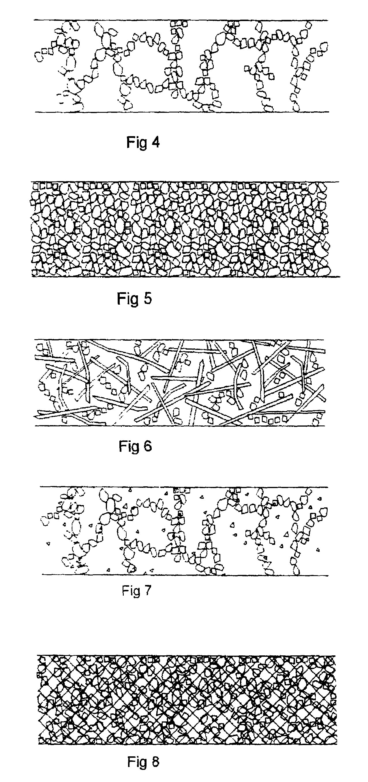
[0017]The conducting tape may be a conducting particle-dispersed plastic or a plastic dispersed carbon tape. For the conducting particle-dispersed plastic tape, the plastic is continuous phase and provides the mechanical strength required by the typical continuous coating equipment used to adhere the actives thereon. Dispersed conducting particles in the tape provide a conducting path for electrical current communicated from the active layer formed on the tape. In the case of plastic dispersed carbon tape, the carbon is the continuous phase and provides not only the required strength during manufacture but also the conducting path for the electrical current. Metallic powders such as Aluminum or Copper may be added to either tape matrix to reduce resistance therein. The electrode formed is thermally stable at high temperatures of at least 240 degrees centigrade which is an important feature since the battery will endure the rigors of solder reflow where the battery is soldered to the circuit board by dipping it in molten solder and affixing directly to the board. Additionally, as earlier noted, flame retardants may be added to the tape matrix to thereby inhibit fire in the battery.
[0018]Since the collector is a polymer or carbon film, the current collector can be compressed during manufacture without damaging the finished battery and providing an outward biasing from inside the battery case to maintain contact pressure between the current collector and the exterior electrical contact.

Problems solved by technology

An existing problem with the manufacture of conventional lithium ion electrodes arises from metal shards that are produced during the slitting process involved in forming the electrodes to the proper dimensions for encasement.
These shards pose a constant danger of damage to the separator and potential shorts between the two electrodes resulting therefrom.
The constant flow of ions in the proximity of the current collector during discharge and charging of the battery has a high potential to cause corrosion of the current collector itself and the contact points with the electrode thereby degrading the communication of electrical current from the adjacent active material of the electrode.
Conventionally, aluminum and copper are especially susceptible to corrosion from the salts in the electrolytes in a lithium ion battery.
Further, there is also a susceptibility to corrosion of current collectors of conventional batteries which can be attributed to inhomogeneous current flow through the current collector itself once it has become corroded and thereby come into uneven contact with the adjacent electrode.
An additional problem with conventionally manufactured lithium ion batteries is the requirement that once manufactured, they must be charged.
This is an expensive and time-consuming step in manufacture.
In dealing with lithium ion batteries there is the further vexing problem of combustion of the highly reactive materials forming the electrodes.
Such corrosion also risks the total failure of the battery should contact be lost between the termination collector such as the current collector or the battery case, and its communicating electrode.
However placement of a flame retardant in the electrolyte as taught by these and other patents inherently complicates the chemistry of the battery since it renders the cell sensitive to voltage and the cell can decompose, as well as limiting the stability of the electrolyte itself.
This makes Dasgupta more expensive and not easily manufactured and fails to address the problem of shards and debris contaminating the electrodes and the need to pre-charge the battery before shipment to avoid corrosion.
However Koshiba fails to address the issue of shards piercing the separator and the potential for corrosion with the metal current collector and the metal powder used therein, the fire hazard, and would still generally require a charging of the battery before storage and shipment.

Method used


Image

  • Fire and corrosion resistant thermally stable electrodes and batteries and method for manufacturing same
  • Fire and corrosion resistant thermally stable electrodes and batteries and method for manufacturing same
  • Fire and corrosion resistant thermally stable electrodes and batteries and method for manufacturing same

Examples


Embodiment Construction

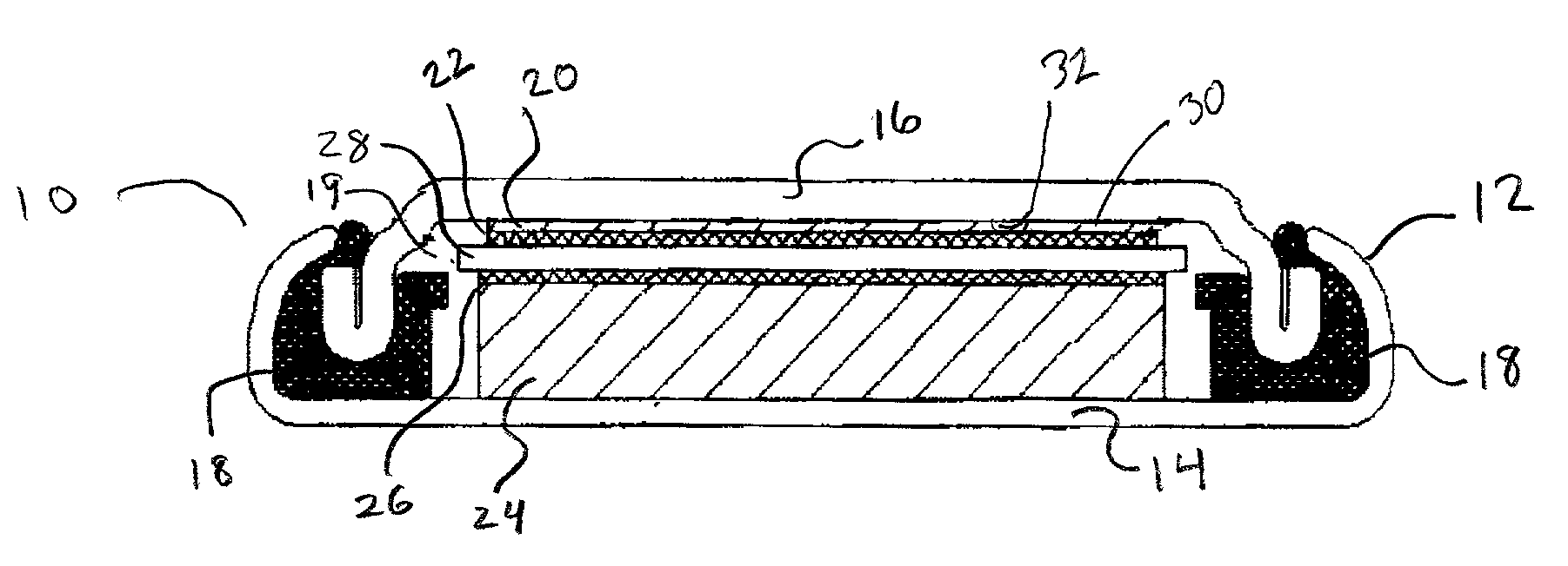
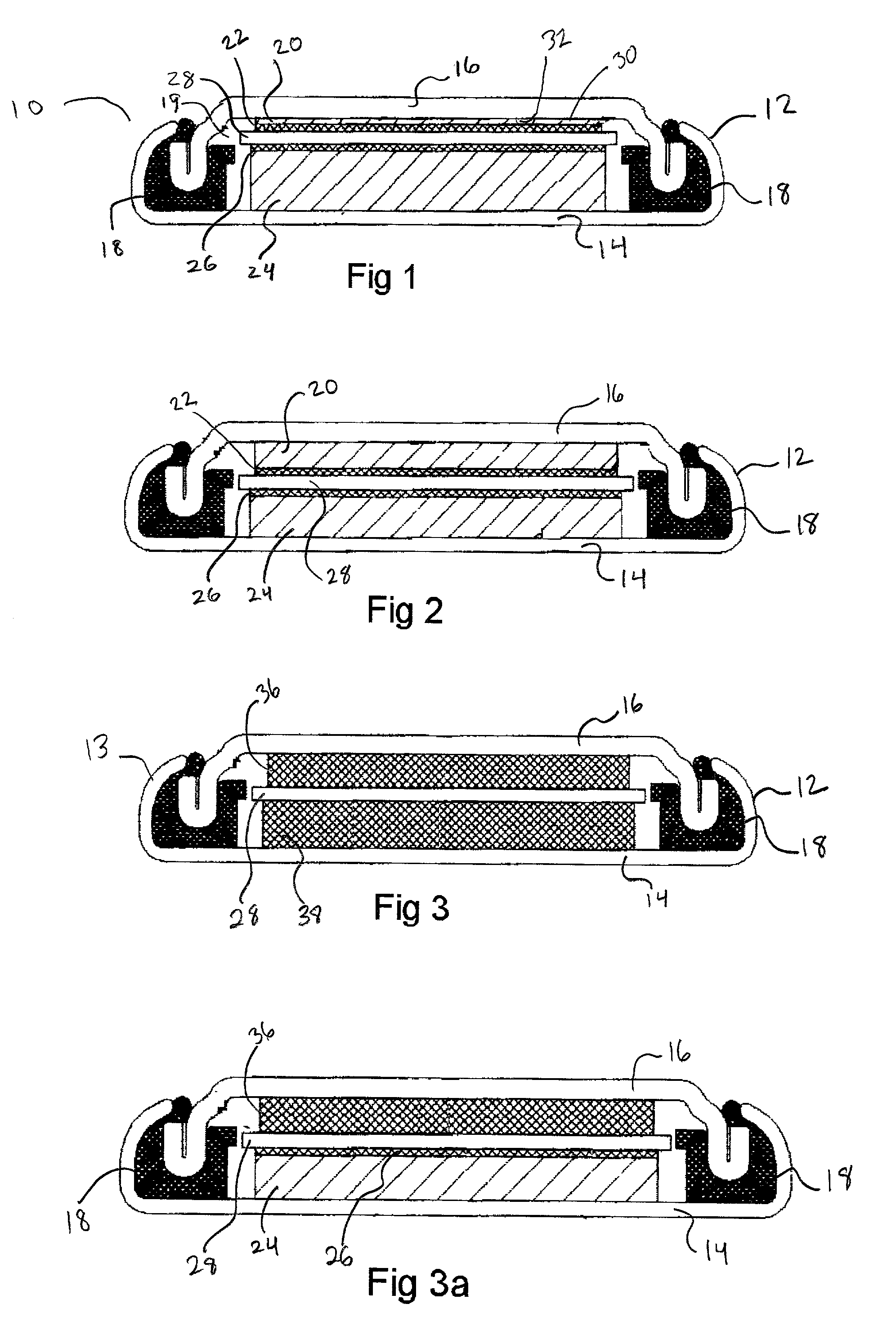
[0039]Referring now to FIG. 1 depicting a side cut away view of a preferred embodiment of the disclosed device 10, the device 10 as assembled forms an electrochemical component or battery and features an assembled cell can 12 formed of a cell casing 14 in sealed engagement with cell cap 16. The sealed engagement of the cell casing 14 with a cell cap 16 is provided through the use of a means for sealed engagement of the cell cap 16 to the cell can 12 which in this case is provided by gasket 18 compressed between the wall of the cell casing 14 and the cell cap 16 and concurrently providing an insulating means between both.

[0040]Inside the internal cavity defined by the interior dimensions of the cell can 12 is a first current collector 20 adjacent to an attached first electrode 22 thereby forming a unitary structure of current collector 20 and electrode 22. Also, in the interior cavity 19 is a second current collector 24 adjacent to an attached second electrode 26 also forming a unita...


PUM

PropertyMeasurementUnit
temperaturesaaaaaaaaaa
conductiveaaaaaaaaaa
fire retardantaaaaaaaaaa

Abstract

An improved battery cell current collectors which are formed as a unitary structure with mating electrodes attached on one surface. The current collectors are formed of non-metallic material including particle-dispersed plastic tape, plastic dispersed carbon tape, fiber dispersed conductive plastic and carbon tape, or particle and metallic powder dispersed conductive tape to resist corrosion. The need to charge the battery immediately after manufacture is eliminated by the improved battery cell design. Additional utility is provided by fire retardant being mixed with one or both of the electrode composite forming the current collectors and the layer forming the current collectors and by the biasing of the current collectors against their terminating contacts by the compressed current collector material communicating a bias of the current collectors against the internal surface of the battery container thereby increasing current flow and decreasing corrosion.

Description

FIELD OF THE INVENTION[0001]The disclosed device relates to electrochemical devices for storing electrical energy. More particularly it relates to the formation of the battery electrodes by adhering the actives forming the electrode directly to the current collectors which are formed of a layer of conductive polymer film or tape.BACKGROUND OF THE INVENTION[0002]Conventional electrochemical devices such as batteries, are used widely in the world as a source of portable electrical power from direct current. Such battery devices provide the electrical power for everything from watches to automobiles and as a consequence great value is placed on the energy density or electrical storage capacity of these devices and their continued ability to provide an adequate supply of electrical current to the communicating electrical device. Currently the lithium ion battery is a preferred battery configuration due to its inherent ability to store and discharge a large volume of electrical power in ...

Claims


Application Information

Patent Timeline
Patent Type & Authority Patents(United States)
IPC IPC(8): H01M4/68H01M2/08H01M6/12H01M4/13H01M4/62H01M4/66H01M10/04H01M10/0525H01M10/42H01M10/44
CPCH01M4/13H01M4/663H01M4/666H01M4/667H01M10/0427H01M10/4235H01M4/668Y02E60/122H01M10/0525H01M10/446Y02E60/10Y02P70/50
Inventor FAN, JIANGMANIS, DAVIDMAGNUSON, DOUGWAN, LU TSE
Owner GP BATTERIES INT LTD
Learn More