
Aerogel composite with fibrous batting

a composite material and fibrous material technology, applied in the field of aerospace composite materials, can solve the problems of relatively low thermal stability in air, unsuitable for most applications outside of the laboratory, and products quite stiff as manufactured, so as to improve the thermal performance of the composite material, improve the thermal performance of the aerogel, and minimize the volume of unsupported aerogel

Inactive Publication Date: 2006-07-18
ASPEN AEROGELS INC
View PDF9 Cites 150 Cited by
  • Summary
  • Abstract
  • Description
  • Claims
  • Application Information

AI Technical Summary

Benefits of technology

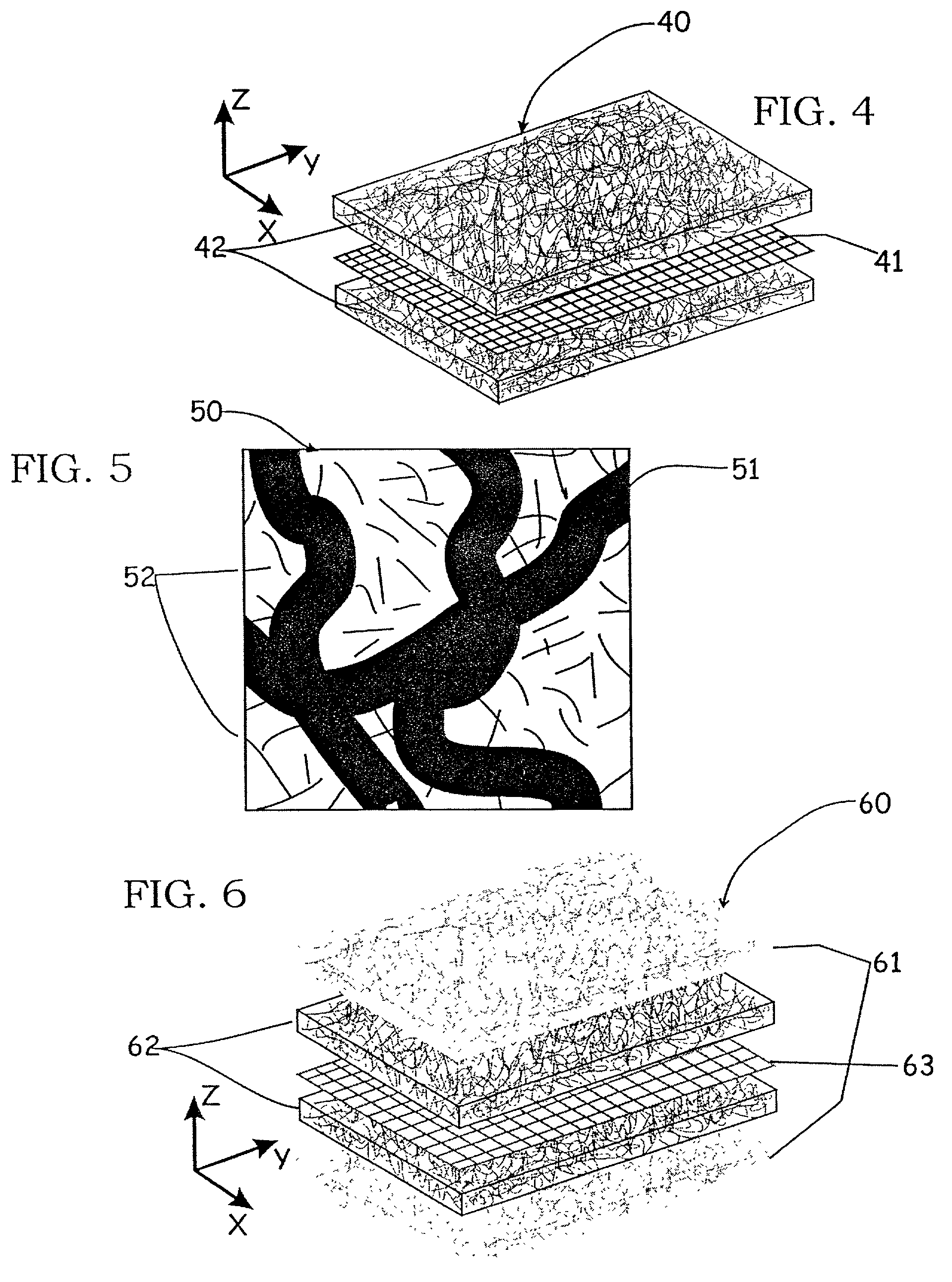
[0014]More specifically, the invention is directed to a composite having two parts, namely reinforcing fibers and an aerogel matrix wherein the reinforcing fibers are in the form of a lofty fibrous structure (i.e. batting), preferably based upon either thermoplastic polyester or silica fibers, and more preferably in combination with individual randomly distributed short fibers (microfibers). The use of the lofty batting reinforcement minimizes the volume of unsupported aerogel while generally improving the thermal performance of the aerogel, rather than degrading it as in the prior art. Moreover, when an aerogel matrix is reinforced by a lofty batting material, particularly a continuous non-woven batting comprised of very low denier fibers, the resulting composite material at least maintains the thermal properties of a monolithic aerogel in highly flexible, drapeable form, making the composite suitable, for instance, for clothing applications.
[0015]Under very high heat loads, such as those generated by direct surface impingement of a gas / oxygen torch flame, monolithic aerogels can rapidly sinter and shrink within seconds. When the aerogels are reinforced by the combination of the lofty fibrous batting and microfibers, as in one embodiment of this invention, the rate of shrinkage, sintering, and ultimate failure of the insulation structure can be delayed by one or more orders of magnitude time, i.e. increasing burn through from seconds to hours.
[0016]Still more specifically, an aerogel composite further including a thermally conductive layer has been found helpful in improving the thermal performance of the composite. For example, carbon fiber cloth or two orthogonal plies of unidirectional carbon fiber placed at the center of a composite provide a thermal breakthrough barrier under a high heat load, a high degree of IR opacification, and a thermally dissipative layer structure that will spread the heat out in the x-y plane of the composite. More specifically, the thermally conductive layer in the middle, through the thickness, of the aerogel composite can be selected to have a minimal effect on the stiffness of the composite. Moreover, if desired the layer can have malleability or intrinsic conformability so that the resulting aerogel composite will be conformable, e.g. a copper wire mesh placed at the interlayer of the aerogel composite article confers conformability and deformability when the composite is bent. In addition, the conductive mesh also provides RFI and EMI resistance.

Problems solved by technology

However, in a monolithic state they tend to be fragile and brittle and are thus not well suited for most applications outside of the laboratory.
The products can be obtained on the scale of about 3–7 hours, but suffer a major drawback of having a high elastic modulus, making the products quite stiff as manufactured.
The products suffer from relatively low thermal stability in air under high heat loads as well as insufficient flexibility for many uses.
Thus flexure of the product resulted in the shedding of significant quantities of the powder.
The prior products were stiff and readily fractured or fragmented.
Thus the prior aerogel composite materials have not been suitable for many uses due to one or more of: low flexibility, low durability, excessive aerogel sintering when exposed to heat, less than ideal thermal conductivity, insufficient x-y thermal and / or electrical conductivity, poor RFI-EMI attenuation, and / or insufficient burn-through resistance.

Method used


Image

  • Aerogel composite with fibrous batting
  • Aerogel composite with fibrous batting
  • Aerogel composite with fibrous batting

Examples


example 1

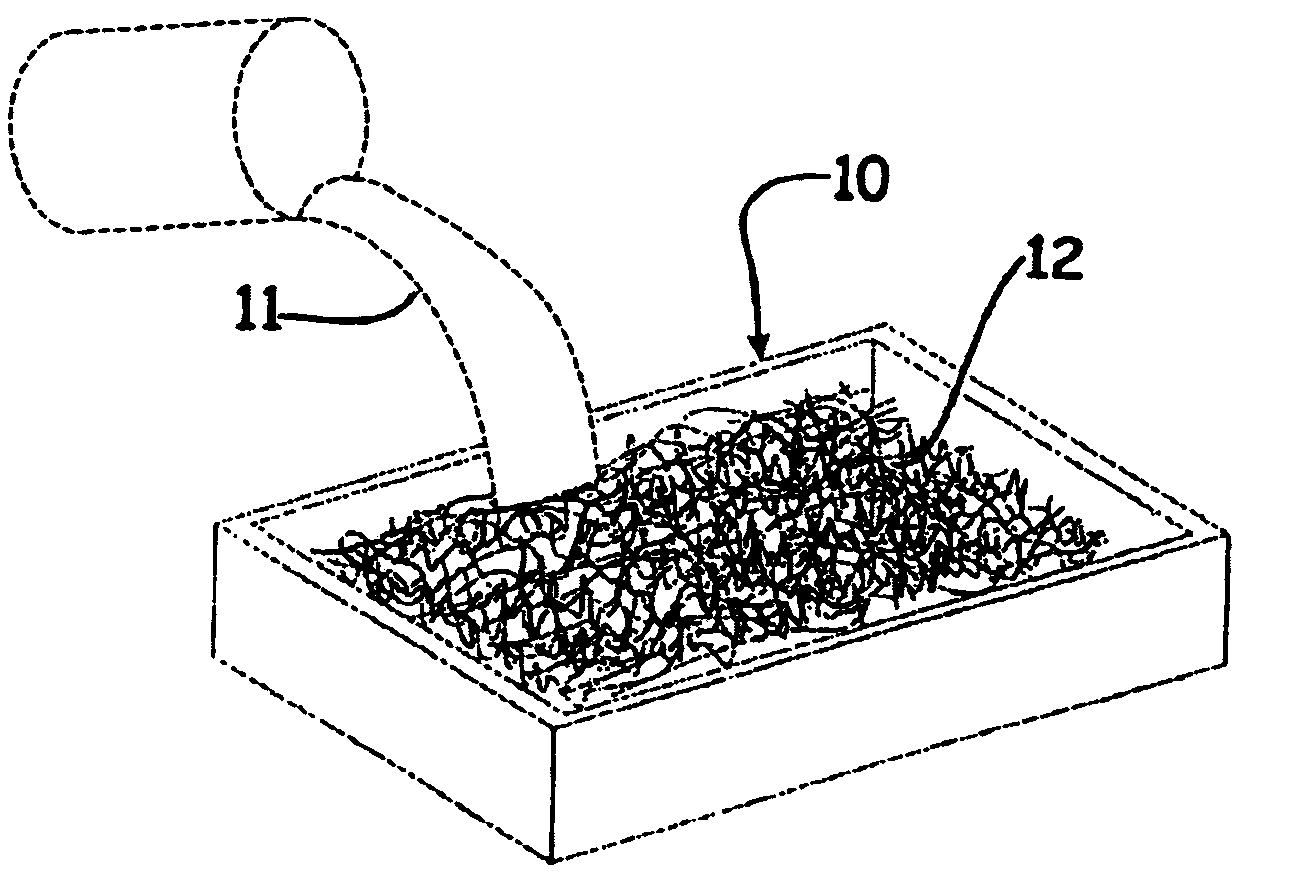
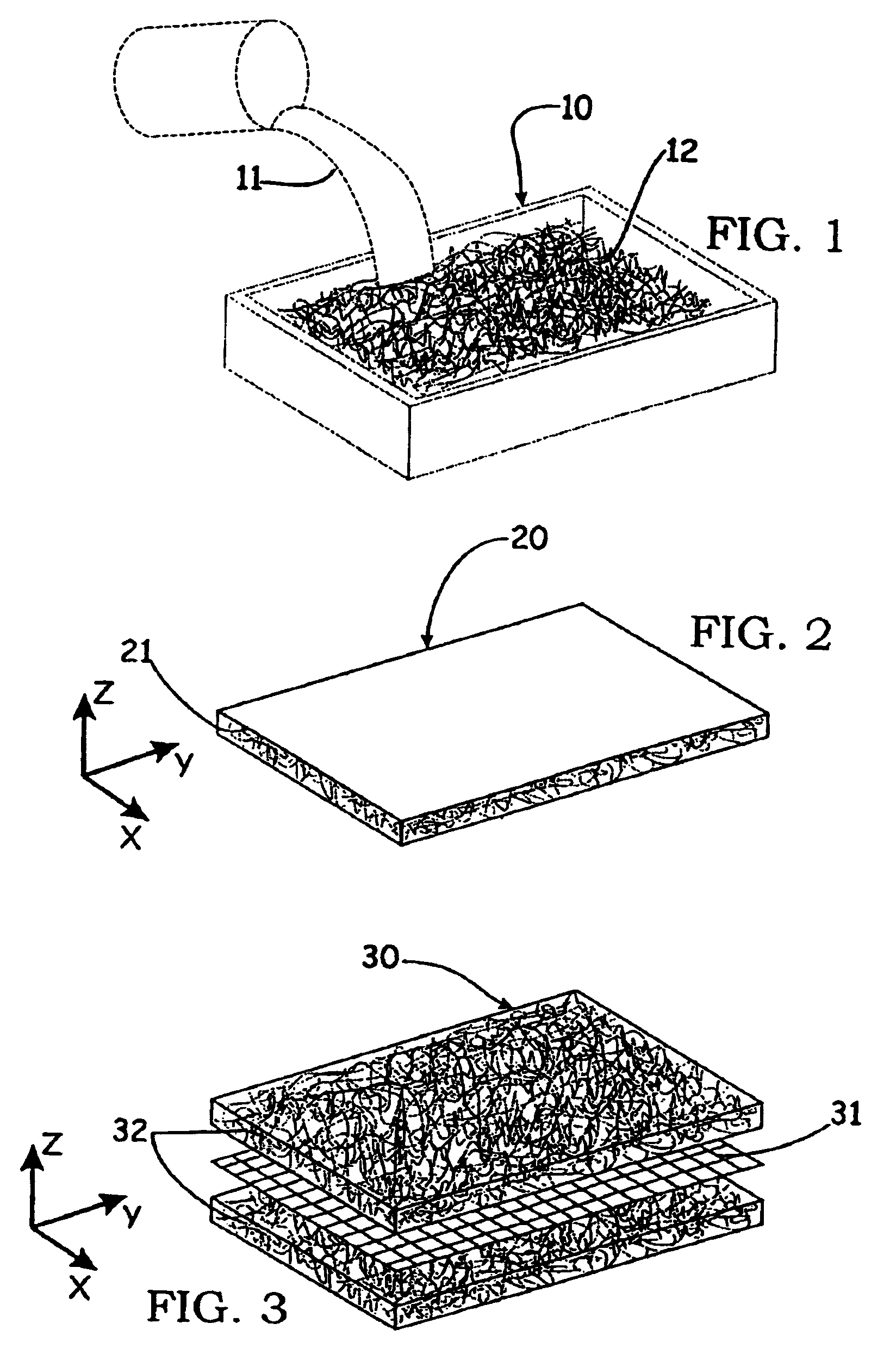
[0064]A section (2′×3′×¼″) of polyester Thinsulate® Lite Loft insulation from 3M Company was placed in a walled container. 1300 ml of a commercially available pre-hydrolyzed silica precursor (Silbond H-5) is mixed with 1700 ml of denatured alcohol, 95%. The solution is stirred for 15 min. The solution is then gelled by the slow addition of HF (2% by volume of the total solution) with stirring. The resulting solution is poured on the blanket previously placed in a container. Gelation occurs within a few minutes. The fresh “blanket-gel” is aged overnight in a sealed bath of ethanol at 50° C. The alcohol trapped in the gel is removed by subcritical and supercritical CO2 extraction over the span of four days.

[0065]The resulting aerogel composite has a density of approximately 0.1 g / cc. The thermal conductivity of the aerogel composite was determined by a Thin Heater Thermal Conductivity Test (ASTM C 1114-98) to be 16.6 mW / m° K. A pure aerogel monolith prepared using the same source mate...

example 2

[0068]The procedure of Example 1 is repeated except that the polyester fiber batting was replaced by a lofty silica fiber structure (Quartzel from Saint-Gobain Quartz) having a density of 65 g / m2 with a polyvinylalcohol binder.

[0069]The resulting silica batting / silica aerogel composite has a thermal conductivity of 15.0 mW / m-K as tested on a guarded hotplate (ASTM C-177). The flexibility of the composite is less than that of the aerogel-polyester blanket of Example 1, but still significant. It is quite flexible but does not drape to the same extent. The density of the aerogel composite was 0.113 g / cc. The thickness of the composite was approximately 3 mm. This composite resists thermal degradation when exposed to open flame much better than the product of Example 1.

[0070]Aerogel sintering appears to be minimized by the presence of the fiber. An oxyacetylene torch is placed 5–6″ below the sample with the top of the flame impinging on the bottom of the blanket. Minimal sintering is se...

example 3

[0071]The procedure of Examples 1 and 2 is repeated except that the reinforcement fiber batting is replaced by a 5 layer fiber laminate of polyester / silicon carbide / -16 copper mesh / silicon carbide / polyester).

[0072]The thermal conductivity (tested per ASTM C-177) is 12.5 mW / m-K (average). The composite is not very flexible. The thickness of the laminate is 10.3 mm. The copper mesh improves the x-y thermal conductivity by spreading out point loads over a larger area. The copper mesh also provides an EMI-RFI shield. Aerogel sintering appears to be minimized by the presence of the reinforcing polyester and silicon carbide fibers.


PUM

PropertyMeasurementUnit
Fractionaaaaaaaaaa
Fractionaaaaaaaaaa
Fractionaaaaaaaaaa

Abstract

Aerogel composite materials having a lofty fibrous batting reinforcement preferably in combination with one or both of individual short randomly oriented microfibers and conductive layers exhibit improved performance in one or all of flexibility, drape, durability, resistance to sintering, x-y thermal conductivity, x-y electrical conductivity, RFI-EMI attenuation, and / or burn-through resistance.

Description

[0001]This application claims the benefit of U.S. Provisional Application No. 60 / 257,437 Dec. 22, 2000.BACKGROUND OF THE INVENTION[0002]The field of the present invention is aerogel composite materials. More particularly, this invention is directed to aerogel composites wherein the resulting composite exhibits improved performance as compared to prior aerogel composite products in one or more of the following qualities: reduced aerogel sintering; higher temperature performance; improved flexibility and drapeability; improved durability; decreased aerogel particle shedding; enhanced x-y plane thermal conductivity; enhanced x-y plane electrical conductivity; enhanced radio frequency interference (RFI) and / or electromagnetic interference (EMI) attenuation, enhanced infrared radiation (IR) suppression; and / or enhanced burn-through resistance. The fiber reinforcement is preferably a combination of a lofty fibrous structure (batting), individual randomly oriented short microfibers, and co...

Claims


Application Information

Patent Timeline
IPC IPC(8): B32B15/04D04H1/02B01J13/00D06M11/79B32B5/26C04B14/06C04B30/02D04H1/00D04H13/00D06M101/40E04B1/76E04B1/78H05K9/00
CPCB01J13/0091C03C13/00C04B14/064C04B30/02D04H13/00D04H13/002E04B1/7662E04B1/78E04B9/045H05K9/009B32B5/26C04B14/34C04B14/386C04B32/02C04B20/006Y10T428/24008C04B2111/00258C04B2111/00413C04B2111/503E04B2001/7687Y02B80/14D04H1/413Y10T442/2926Y10T442/2475Y10T442/2984Y10T428/249924Y10T442/624Y10T442/622Y10T442/2918Y10T442/2869Y10T428/249964Y10T442/20Y10T442/2902Y10T442/291Y10T428/249962Y10T442/2631Y10T442/60Y10T442/2861Y10T428/249965Y02A30/24Y02B80/10B32B15/02B32B15/14B32B15/18B32B15/20B32B2305/38B32B2307/718B32B2250/20B32B2250/40
Inventor STEPANIAN, CHRISTOPHER J.GOULD, GEORGE L.BEGAG, REDOUANE
Owner ASPEN AEROGELS INC
Learn More