Patch antenna apparatus preferable for receiving ground wave and signal wave from low elevation angle satellite

a technology of patch antenna and antenna, which is applied in the structure of radiating elements, waveguide devices, resonance antennas, etc., can solve the problems of inconvenient use of antennas having the maximum radiation direction at the zenith for receiving ground waves from repeaters, antennas that cannot efficiently receive ground waves, and antennas with the maximum radiation direction at the zenith cannot be suitable for receiving ground waves. , to achieve the effect of reducing gain, efficient receiving ground waves and signal waves,

Active Publication Date: 2006-07-18
ALPS ALPINE CO LTD
View PDF6 Cites 20 Cited by
  • Summary
  • Abstract
  • Description
  • Claims
  • Application Information

AI Technical Summary

Benefits of technology

[0017]With this arrangement, radio waves radiated in response to a change in the electric field between the patch electrode and the ground substrate can be received and re-radiated by the metal pins. The maximum radiation direction of the radio waves radiated from the patch electrode serving as a radiating conductor is directly above. In contrast, the maximum radiation direction of the radio waves re-radiated from each the upright portion of each metal pin serving as a radiating conductor is horizontal, in the same manner as a monopole antenna. Thus, a combined radiation pattern of both the radio waves has a flattened shape compressed from directly above. This patch antenna apparatus, therefore, has a reduced gain directly above the patch electrode and its maximum radiation direction changes from directly above the patch electrode to obliquely upward. That is, the beams are shaped so that the maximum radiation direction is at a low elevation angle. Thus, even when installed on the roof surface of a vehicle or the like, this patch antenna apparatus can efficiently receive ground waves and signal waves from a low elevation-angle satellite.
[0018]In this embodiment, each metal pin may be a pin member in which the upper end of the upright portion is bent and the lateral metal member extends from the bent portion. This can provide a simple structure. Preferably, the metal pin has a substantially L shape in which the upper end of the upright portion is bent at a substantially right angle. This arrangement can reduce the height dimension.

Problems solved by technology

However, the patch antennas having a maximum radiation direction at the zenith cannot efficiently receive ground waves.
Thus, in a system in which a ground-based repeater receives signal waves from a satellite (e.g., an S-band digital audio radio satellite currently being planned) and re-transmits the signal waves, when such a known patch antenna is installed on the roof surface of a vehicle or the like, the antenna cannot be used as a planar antenna for receiving ground waves from the repeater.
Also, the antennas having the maximum radiation direction at the zenith are not suitable for receiving signal waves from a low elevation-angle satellite.

Method used


Image

  • Patch antenna apparatus preferable for receiving ground wave and signal wave from low elevation angle satellite
  • Patch antenna apparatus preferable for receiving ground wave and signal wave from low elevation angle satellite
  • Patch antenna apparatus preferable for receiving ground wave and signal wave from low elevation angle satellite

Examples


first embodiment

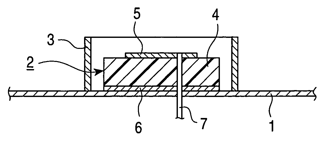
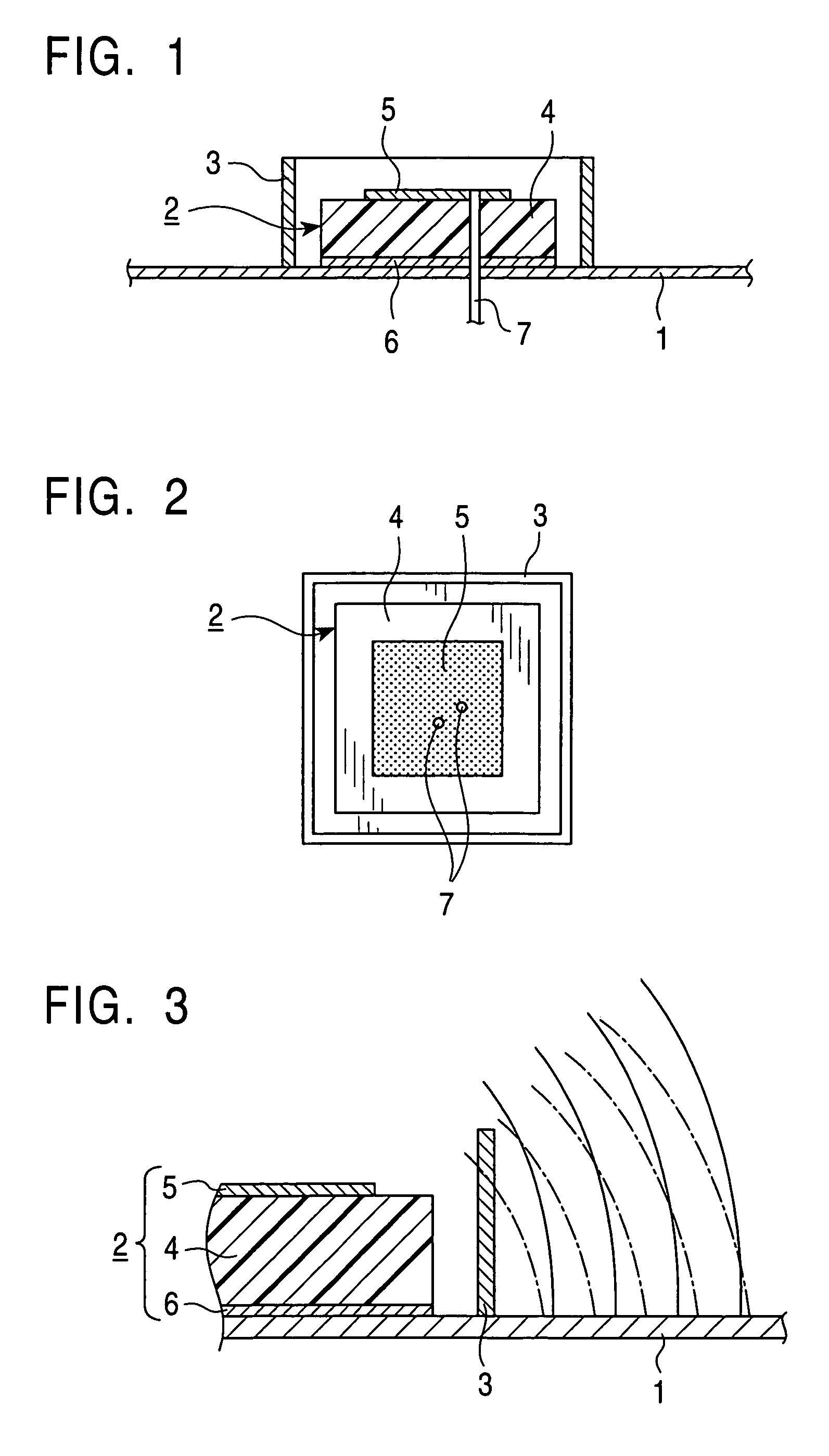
[0032]As described above, in the patch antenna apparatus the metal frame 3 is disposed around the dielectric substrate 4, to thereby reduce the gain directly above the patch electrode 5. Thus, the beams are shaped so that the maximum radiation direction is at a low elevation angle. The patch antenna apparatus, therefore, can receive incoming signal waves even at an elevation angle of about 20°. Accordingly, even when installed on the roof surface of a vehicle or the like, the patch antenna apparatus can efficiently receive ground waves and signal waves from a low elevation-angle satellite, and thus can be used as a vehicle-mounted small antenna that is preferable for S-band radio broadcasting and the like.

[0033]As in the embodiment described above, the plan view shape of the metal frame is preferably similar to that of the outer shape of the dielectric substrate 4, since the space factor improves. However, even if they don't have a similar plan view, substantially the same beam sha...

second embodiment

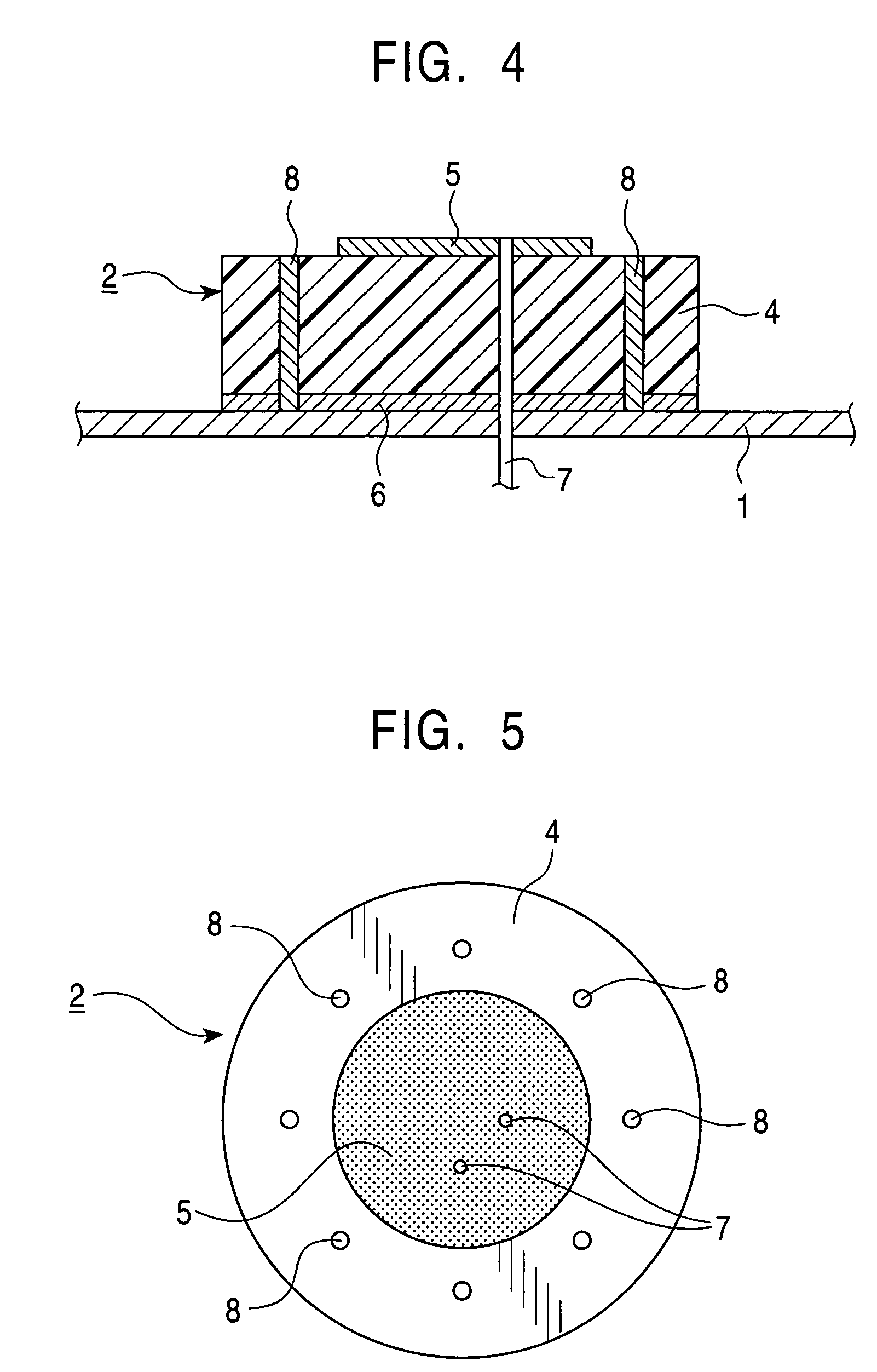
[0039]As described above, in the patch antenna apparatus the plurality of metal pins 8 are arranged in the dielectric substrate 4 along the circumference direction thereof. Thus, the gain directly above the patch electrode 5 is reduced, and the beams are shaped such that the maximum radiation direction is at a low elevation angle. This patch antenna apparatus, therefore, can receive incoming signal waves even at an elevation angle of about 20°. Accordingly, even when installed on the roof surface of a vehicle or the like, this patch antenna apparatus can efficiently receive ground waves and signal waves from a low elevation-angle satellite, and thus can be used as a vehicle-mounted small antenna that is preferable for S-band radio broadcasting and the like.

[0040]While eight metal pins 8 are provided in the dielectric substrate 4 along the circumference direction thereof in the above-described embodiment, arranging three or more metal pins 8 at regular intervals allows all direction...


PUM


Abstract

A patch antenna apparatus includes an antenna element and a metal frame, which are disposed on a ground plane. The antenna element has a dielectric substrate, which has a patch electrode on the top surface and has a ground electrode on the bottom surface. The patch electrode is connected to current-feed pins. The metal frame is positioned so as to surround the peripheral surface of the dielectric substrate. The height dimension of the metal frame is set to be slightly larger than the thickness dimension of the dielectric substrate. Electromagnetic radiation radiated from the antenna element is reflected upon reaching the metal frame. Thus, the metal frame causes interference with the electromagnetic radiation such that the traveling direction of the electromagnetic radiation is redirected closer to the lateral direction.

Description

[0001]This application claims the benefit of Japanese Patent Applications 2003-105565, 2003-105561, and 2003-105401, filed on Apr. 9, 2003, which are incorporated herein by reference.BACKGROUND OF THE INVENTION[0002]1. Field of the Invention[0003]The present invention relates to a patch antenna apparatus for use as a vehicle-mounted small antenna or the like, and more particularly, to beam shaping of the radiation patterns of the patch antenna apparatus.[0004]2. Description of the Related Art[0005]Patch antennas are planar antennas in which a dielectric substrate having a patch electrode on the top surface is disposed on a ground plane and a predetermined high-frequency current is fed to the patch electrode via current-feed pins or the like. The patch antennas are widely used as vehicle-mounted small antennas and the like for receiving satellite waves. In order for the patch antennas to achieve a high gain, the ground plane needs to have a sufficiently large area compared to the pat...

Claims


Application Information

Patent Timeline
Patent Type & Authority Patents(United States)
IPC IPC(8): H01Q1/38H01Q1/42H01P1/38H01P9/04
CPCH01P9/04H01P1/38
Inventor YUANZHU, DOU
Owner ALPS ALPINE CO LTD
Why Eureka
Try Eureka