Method of noise cancellation in an unpolarized-laser instrument

a technology of laser instruments and noise cancellation, applied in instruments, optical radiation measurement, therapy, etc., can solve the problems of increased particle size, reduced instrument sensitivity, and increased noise reduction, so as to improve the signal-to-noise ratio and improve the effect of noise cancellation

Active Publication Date: 2006-07-18
EXCELITAS TECH
View PDF21 Cites 3 Cited by
  • Summary
  • Abstract
  • Description
  • Claims
  • Application Information

AI Technical Summary

Benefits of technology

[0006]Provided is an improved method for canceling noise in an instrument which uses an unpolarized laser, and a system having improved noise cancellation. This invention improves the direct subtraction method described above, wherein the laser amplitude fluctuations are subtracted from a desired signal to create a desired signal having an improved signal-to-noise ratio. This invention recognizes the different polarization sensitivities that a reference monitor of the laser power and a detector of desired signals (for example, a scattered light detector) have and corrects the subtraction accordingly. This invention is useful in any system that contains two (or more) detectors with unequal sensitivities to the polarizations of light in which the signals of both detectors contain at least one of the same noise sources and only one of the detector's signals contains the desired signal.
[0007]Generally, a laser power reference detector that monitors the power of a laser (reference monitor detector) is positioned at a first angle with respect to the laser beam axis. The laser beam axis is defined as the axis along which the laser beam travels. The reference monitor detector may be positioned anywhere in the system as long as it detects the power of the laser and does not contain the desired signal. The reference monitor detector may be positioned along the laser beam axis, or at any angle with respect to the laser beam axis, as long as the angle of the reference monitor detector with respect to the laser beam axis is not the same as the angle of the signal detector with respect to the laser beam axis. The laser light of the first and second detectors can be decomposed into two orthogonal polarization states. For sake of clarity, the reference detector is taken to be along the output of the laser and the decomposition described herein is in terms of the linear polarizations termed s- and p-polarizations. These are defined specifically below. The invention does not rely on any particular decomposition of polarization. The reference monitor detector has a different sensitivity to the s- and p-polarizations of the laser beam than a signal detector positioned at a different angle with respect to the laser beam axis (for example a scattering detector used to detect scattered light from particles or molecules in the laser path) has because of the geometry of the system. This invention corrects the sensitivity of the reference monitor detector and the signal detector so that both detectors have the same sensitivity to the polarizations of the light prior to subtraction of the monitored laser reference signal from the signal at the signal detector. The correction described herein improves the noise cancellation in the desired signal. The correction can be carried out in different ways, as further described herein.
[0009]In another embodiment, provided is a method of reducing technical background scattering in the presence of polarization mode fluctuations from a detected signal comprising: separating the output of a laser source into orthogonal polarization components; detecting the intensity of the orthogonal polarization components using a first detecting element positioned at a first angle with respect to the laser beam axis, adjusting the relative intensity of the orthogonal polarization components and the overall intensity of the orthogonal polarization components so that the relative and overall intensity of the orthogonal polarization components at the first detecting element matches that of a second detecting element positioned at a second angle with respect to the laser beam axis, forming a polarization correction; and subtracting the polarization correction from the detected signal at the second detector, whereby the technical background scattering is reduced.
[0013]a gain element in electrical connection with the detector; a scattering light detector positioned at a second selected angle which is not along the light path, in optical communication with the output of the laser; means for adjusting the adjustable polarizing element and the gain element so that the noise detected at the scattering light detector is reduced.

Problems solved by technology

The background scattering noise reduces the sensitivity of the instrument.
Shot noise is not reducible.
However, there are other sources of noise (technical background scattering) that result in lowered sensitivity and therefore, result in an increase in the size of the smallest detectable particle.
One of these additional sources of noise comes from laser amplitude fluctuations.
This type of direct subtraction, however, does not work as well as expected in an unpolarized laser system.
Polarization mode fluctuations give rise to an additional noise term that cannot be directly subtracted.
The noise caused by polarization mode fluctuations is not generally appreciated.
Therefore, if a direct subtraction method is used for technical background scattering, there is imperfect noise cancellation of laser amplitude fluctuations.
None of the described methods of noise reduction takes into account the effect of polarization mode fluctuations on technical background scattering.

Method used


Image

  • Method of noise cancellation in an unpolarized-laser instrument
  • Method of noise cancellation in an unpolarized-laser instrument
  • Method of noise cancellation in an unpolarized-laser instrument

Examples


second embodiment

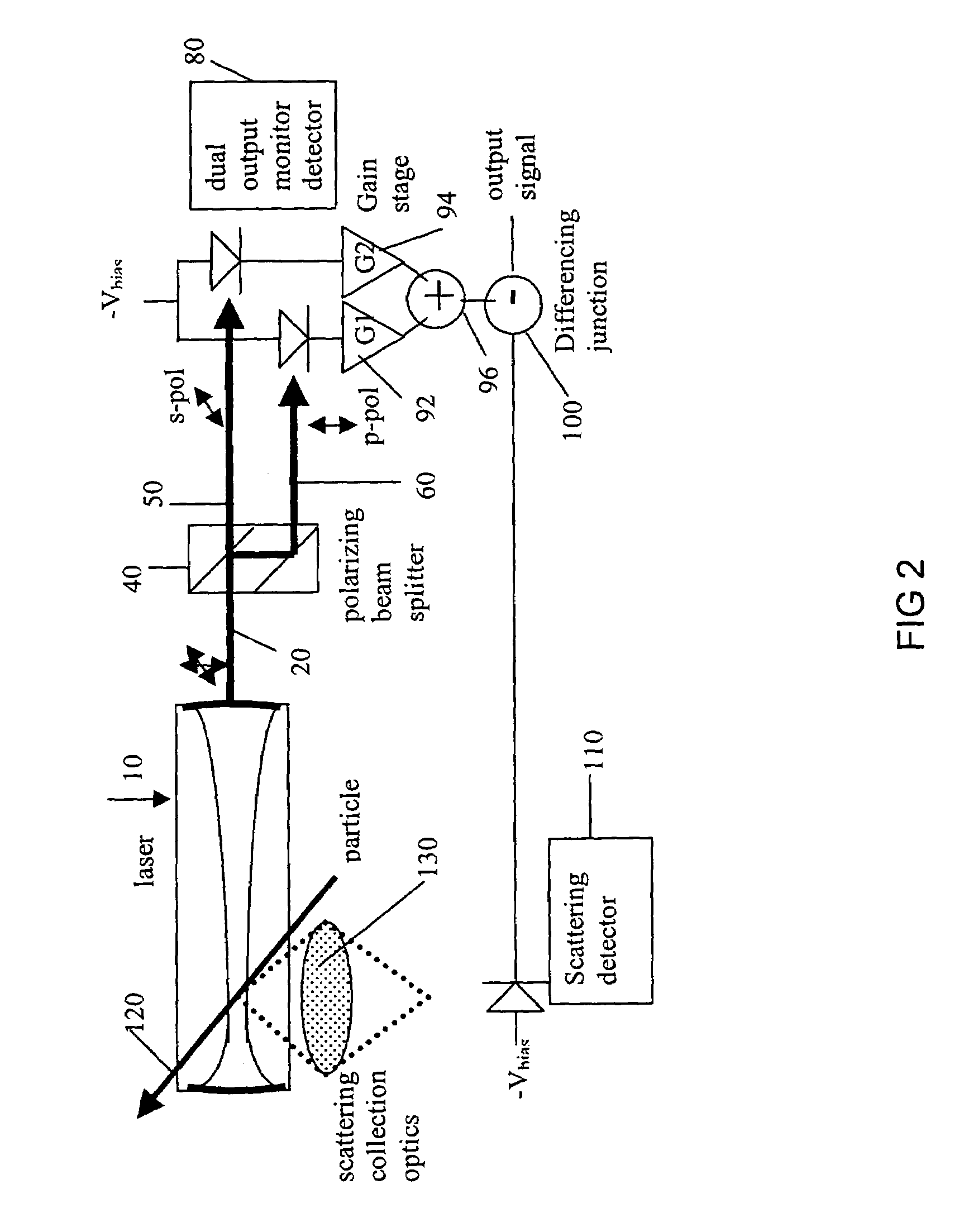
[0035]In a second embodiment, shown in FIG. 2, the instrument is the same as shown in FIG. 1, except the sheet polarizer is removed. The spatially-separated s- and p-polarization components each illuminate their own detector. Each detector is then electrically connected to its own gain stage (92 and 94). The two gain stages G1 (92) and G2 (94) together provide both relative control and overall control and are set appropriately for maximum noise cancellation. The two gain stages are electrically summed (96) and then sent on to differencing junction (100).

third embodiment

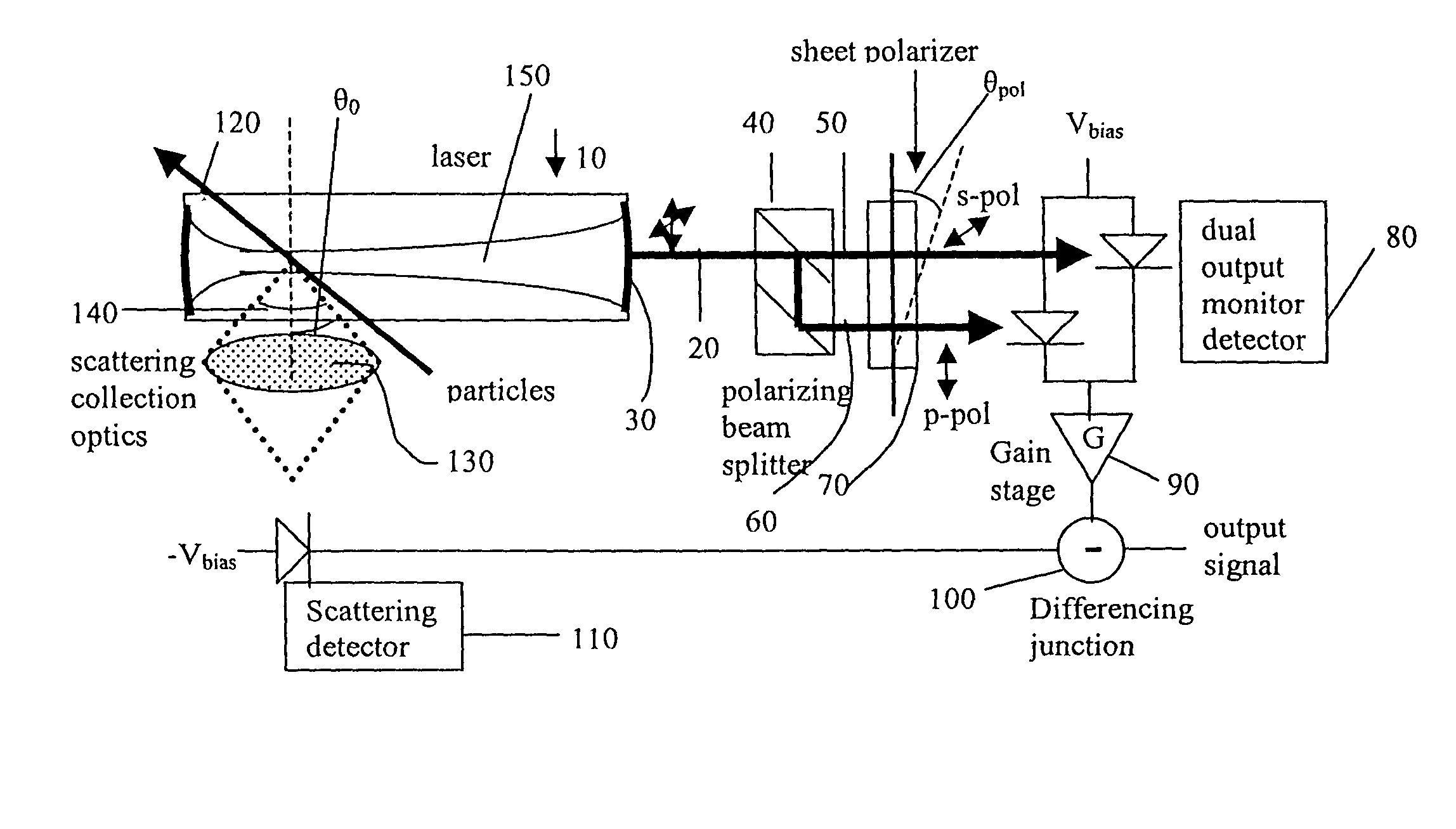
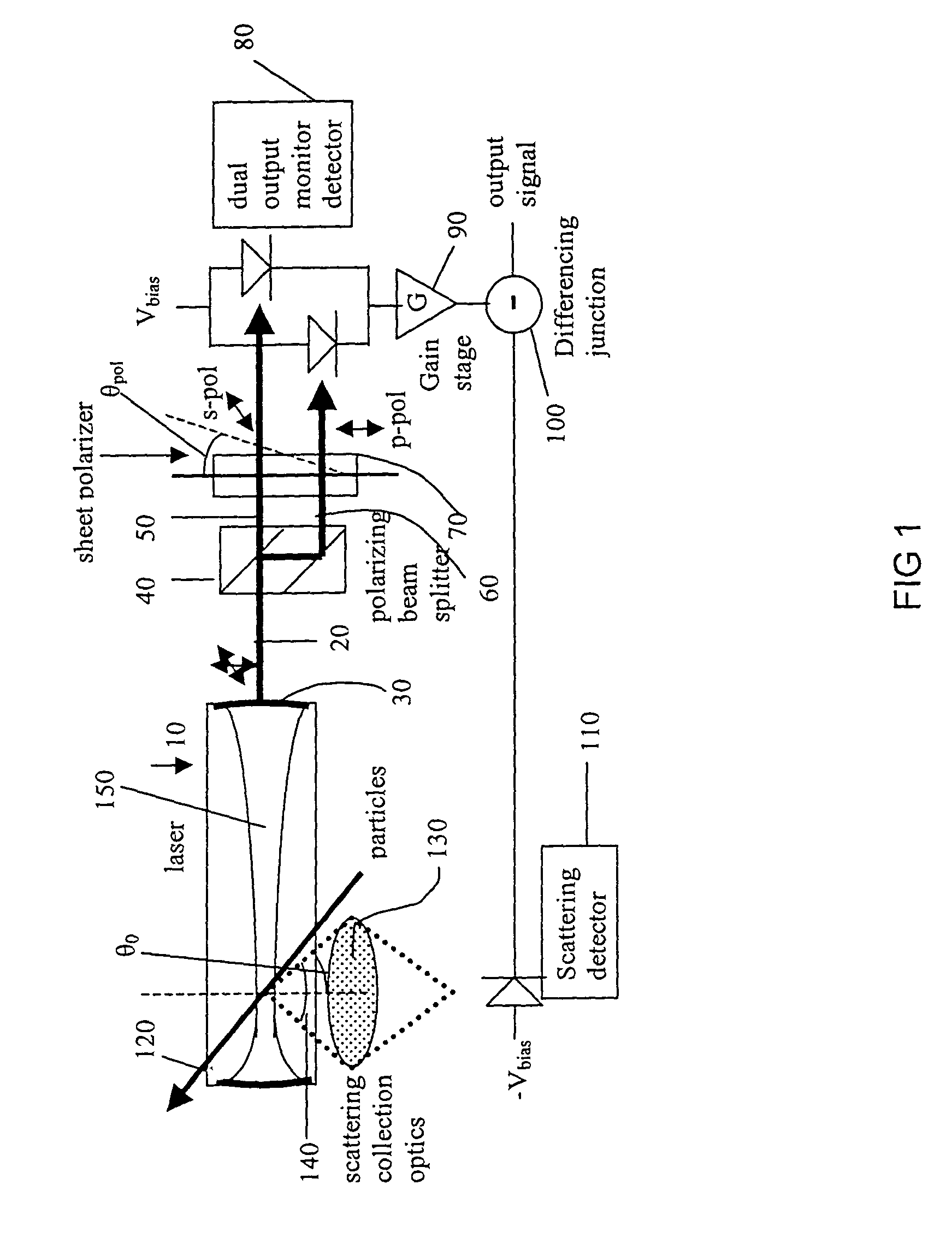
[0036]In a third embodiment, shown in FIG. 3, there is only a single polarizer (70) (which can be a sheet polarizer or other polarizer, as known in the art) and a single detector (82). There is thus no separation of the s- and p-polarization components. In the embodiment shown in FIG. 3, the angle of the polarizer 70 and the gain 90 are set so that the signal at 82 is the same as the signal at 110 when no particles are present in laser 10.

[0037]The first two embodiments described give noise cancellation of about a factor of 10 as compared to an uncorrected system. The third embodiment described gives a lower level of noise cancellation.

[0038]In a specific preferred embodiment, the invention is incorporated in an instrument based on a Helium-Neon laser used to detect and size particles passing through the intracavity laser beam. The laser cavity is formed by two mirrors, both of which have reflectivities around 99.99%. The intracavity power is on the order of 40 Watts. Some of the li...


PUM

PropertyMeasurementUnit
diameteraaaaaaaaaa
poweraaaaaaaaaa
diameteraaaaaaaaaa

Abstract

A method of noise reduction in a system where polarization mode fluctuations contribute to the noise in a signal is provided. Specifically, a corrected signal is formed by adjusting the relative and overall intensity of the orthogonal polarization components of an unpolarized laser source at a first detector positioned at a first angle with respect to the laser beam axis so that the first detector has the same sensitivity to polarization as a second detector positioned at a second angle with respect to the laser beam axis. This corrected signal is then subtracted from the signal at the second detector which detects a desired signal.

Description

CROSS REFERENCE TO RELATED APPLICATIONS[0001]This application claims the benefit of U.S. Provisional Application No. 60 / 396,311 filed Jul. 16, 2002, which is incorporated by reference to the extent not inconsistent with the disclosure herewith.BACKGROUND OF THE INVENTION[0002]Unpolarized lasers are commonly used in a variety of applications, including instruments to optically detect and size particles down to 0.1 microns in diameter. These instruments measure the light scattered from particles as they pass through the laser beam. Determination of the size of the particle is determined by the amount of scattered light that is detected. The noise floor in these instruments comes from light scattered by the background molecular gas in the particle-laser interaction region (background scattering noise) and is of two types: a fundamental noise from the photon statistics (shot noise) present even in a perfect laser and technical background scattering noise from an imperfect laser source (...

Claims


Application Information

Patent Timeline
Patent Type & Authority Patents(United States)
IPC IPC(8): G01N21/00G01J4/00A61NG01J1/04G01J1/08G01J1/42G01N15/02G01N15/14
CPCG01J1/04G01J1/4228G01J1/08G01J1/0429
Inventor SANDBERG, JON C.TURCHETTE, QUENTIN A.
Owner EXCELITAS TECH
Why Eureka
Try Eureka