Modularized insulation, systems, apparatus, and methods

a technology of modular insulation and insulation properties, applied in heat-proofing, natural mineral layered products, transportation and packaging, etc., can solve the problems of shortening the useful life of aircraft, affecting the efficiency of aircraft, so as to reduce the cost and labor intensity of installation, prevent or minimize the shifting of batting blocks, and reduce the effect of insulation properties

Active Publication Date: 2006-08-01
THE BOEING CO
View PDF112 Cites 77 Cited by
  • Summary
  • Abstract
  • Description
  • Claims
  • Application Information

AI Technical Summary

Benefits of technology

[0016]In the aforementioned and other embodiments of the invention, the distal and proximal layers of the insulation blanket of the invention each have an interior cover surface and an exterior cover surface and each of the plurality of batting blocks are attached to at least one interior cover surface of the module in which said batting block is disposed. This helps to prevent or minimize shifting of the batting blocks within the modules.
[0017]Further, in the aforementioned and other embodiments, at least one of the heat-sealed seams may be perforated to provide a tear-line in a foldable heat-sealed seam or in a perforated foldable heat-sealed seam, which may be referred to as a tearable heat-sealed seam. The tear-line allow for sizing of the blanket by cutting or tearing along the tear-line without exposing the batting or possibility of batting fibers becoming airborne. This method of sizing is both less expensive and labor intensive than that of the prior art. Foldable heat-sealed seams and the compressible folds thereof have some limited spring like attributes and can provide lateral support and stability to blankets installed between struts of a structure. Further, compressed folds may act as a stop against compression of the batting which can result in diminished or loss of insulation properties. Prior art blankets do not have such folds or foldable heat-sealed seams and cannot provide these advantages and features provided in certain embodiments of the invention.
[0019]In the aforementioned and yet other embodiments of the invention, the modular insulation blanket may be provided with retention systems or a plurality of attachment means affixed to an exterior surface a cover layer, typically the proximal layer but the distal layer may also be provided with such retention system or plurality of attachment means. Thus, embodiments of the invention may further comprise a retention system or a plurality of attachment means selected from the group consisting of a mated mechanical attachment system, a peel-and-stick tape system, a hook-loop retention system, tape, combined hook and loop and peel and stick tape retention systems, self-adhering retention systems, adhesives, a plurality of mechanical fasteners, and combinations thereof. Providing such retention systems as part of some embodiments of the insulation blanket of the invention allows for ease of installation without the significant surface preparation and attendant labor and costs. Further, they allow for blanket installation with a constant interface, minimizing or eliminating the pocketing and pooling and the associated negative effects seen in prior art insulation blankets.
[0021]The aforementioned and other embodiments of methods of the invention may further comprise the step of perforating at least one of the heat sealed seams to provide a tearable heat sealed seam and / or perforating the distal layer and / or the proximal cover layer to provide a breathing system in each of the plurality of modules. Tearable heat seal seams can be cut or torn for sizing of blankets according to the invention without exposing the batting or risk of fibers becoming airborne which frequently occurs with sizing of prior art blankets during installation.
[0028]In the various embodiments of an apparatus of the invention, platen may be a unitary element or the portions of platens in alignment with heating elements or heat seal rollers may be removable platen sections. Removable platen sections may be configured to provide different types of heat-sealed seams, providing flexibility without need for multiple apparatus separately configured to manufacture blankets according to the invention with different types of seams.

Problems solved by technology

Commercial and other aircraft may experience extremely high moisture condensation and associated water leakage through overhead panels due to a phenomena commonly referred to in the commercial airplane industry as “Rain-in-the-Plane.” This problem originates moisture contributions from various sources, including the environmental control systems, conditioned air duct distribution systems, internal-external temperature differentials, and passenger breathing.
When released, the condensate often affects electrical systems housed behind and on ceiling panels, can cause corrosion and shorten aircraft useful life.
Damaged electrical systems can cause equipment failure and dangerous operational malfunctions, requiring equipment repair and replacement or initiation of in flight emergency landing procedures, such as fuel dumping and premature landings at the nearest available airport.
The negative affects of condensed moisture in aircraft and related emergency measures can result in significant economic losses due to costs associated with fuel dumping, lost flight time due to grounding of out-of-service aircraft, passenger discomfort, inconvenience and lack of confidence, and required systems analyses and repairs.
These losses are currently being incurred by the commercial airplane industry with the use of conventional insulation systems.
Without breathers, some insulation blankets may balloon and possibly rupture.
Batting 12 is prone to shifting within prior art blanket 10 after installation over a period of use due to gravitational, vibrational and impact forces and can cause bulking or gathering at the lowest point of prior art blanket 10 when attached to a vertical or arcuate surface.
This can also be a problem on vertical and horizontal surfaces to which insulating blankets are improperly installed without attention to assuring that the blanket and surface are in constant interface.
Such improper installation may reduce the effectiveness of the insulation.
Further, it may result in “pockets” or “pocketing” where moisture accumulated within the blanket or its batting may pool or in pooling of condensate between the blanket and the horizontal or arcuate surface.
Bulking, pocketing and pooling negatively impact the thermal and / or acoustical performance of the blanket and may promote Rain-in-the-Plane.
Even with such a stockpile of standardized blankets, there remain a number of applications for which these prior art blankets are not a good fit.
Such applications require, extensive reworking of the blankets.
This is not only a labor intensive effort, but an inefficient fix, both in terms of blanket integrity and performance, as well as in time and expense.
Further, it exposes the workers to contact with the batting fibers.
Excessive handling of and contact with batting material can result in skin contact with the fibers and cause shedding of fibers which can be come airborne.
Exposure to batting fibers is known to have the potential for deleterious human health effects, such as skin irritations (e.g., swelling, break-out, and rush) and negative respirator and breathing impacts.
Installation methods for prior art insulation blankets in aircraft are labor intensive, requiring expensive hardware and long set-up times to position blankets, identify tie-points, mark attachment points, coordinate mating points with stand-offs, apply the stand-offs (typically with adhesives), cure adhesives, and provide breathers or breathing systems.
Prior art blankets can be heavy and cumbersome, making for difficult handling.
Despite best efforts, prior art installation methods are susceptible to error and to inconsistencies which can lead to the pocketing problems previously mentioned.
Customizing to unique customer aircraft components, inconsistent draping of insulation blankets around curvatures, inadequate tension, failure to provide constant interfaces and the like also contribute to installation errors and pocketing.
This essentially results in a space with minimal to no effective insulation.
An even greater space is needed between adjacent prior art blanket sections on a length of pipe or duct, resulting in reduced or less than optimal insulation.

Method used


Image

  • Modularized insulation, systems, apparatus, and methods
  • Modularized insulation, systems, apparatus, and methods
  • Modularized insulation, systems, apparatus, and methods

Examples


Embodiment Construction

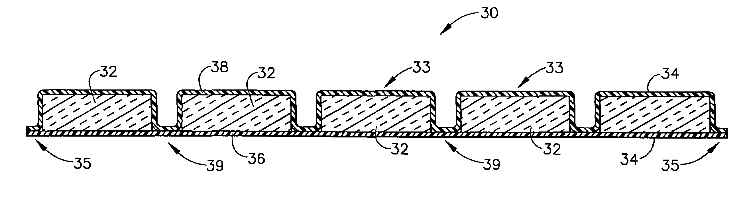
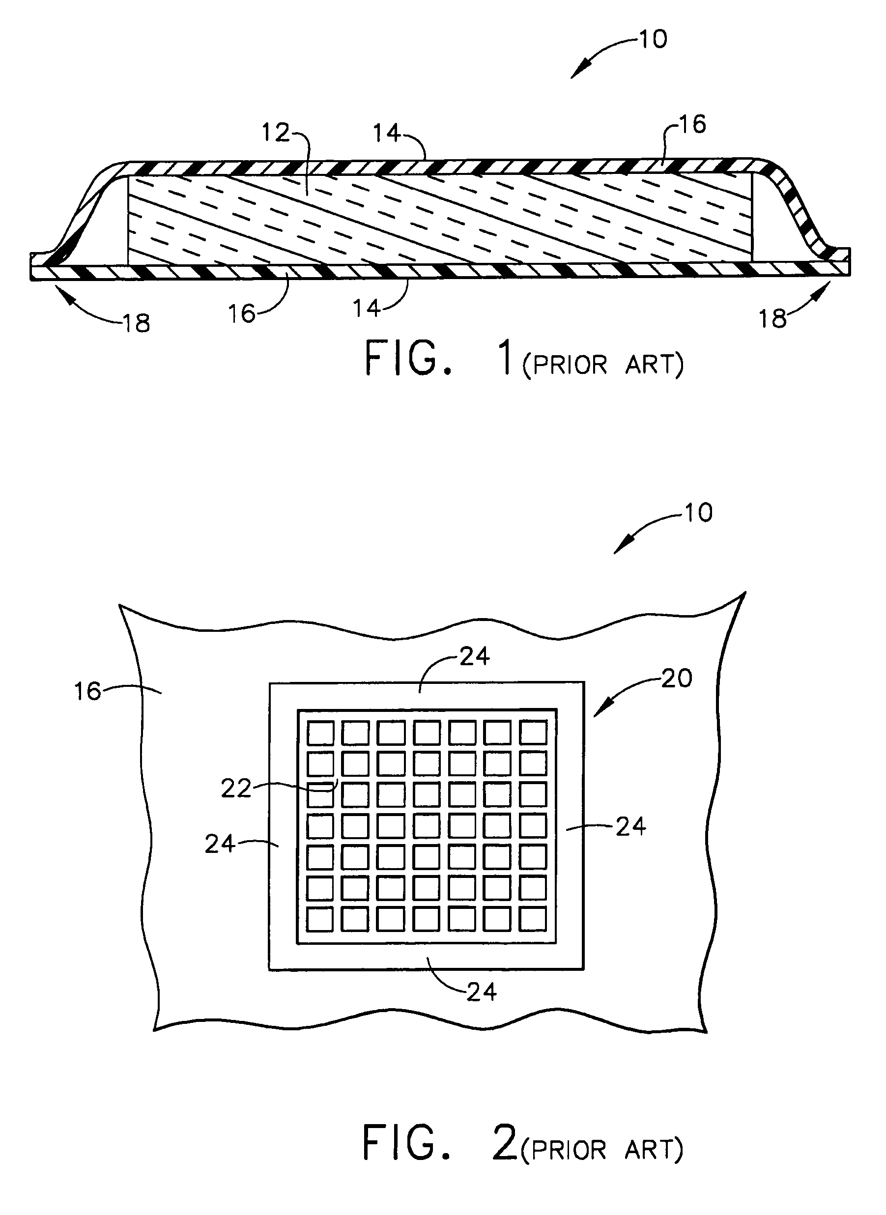
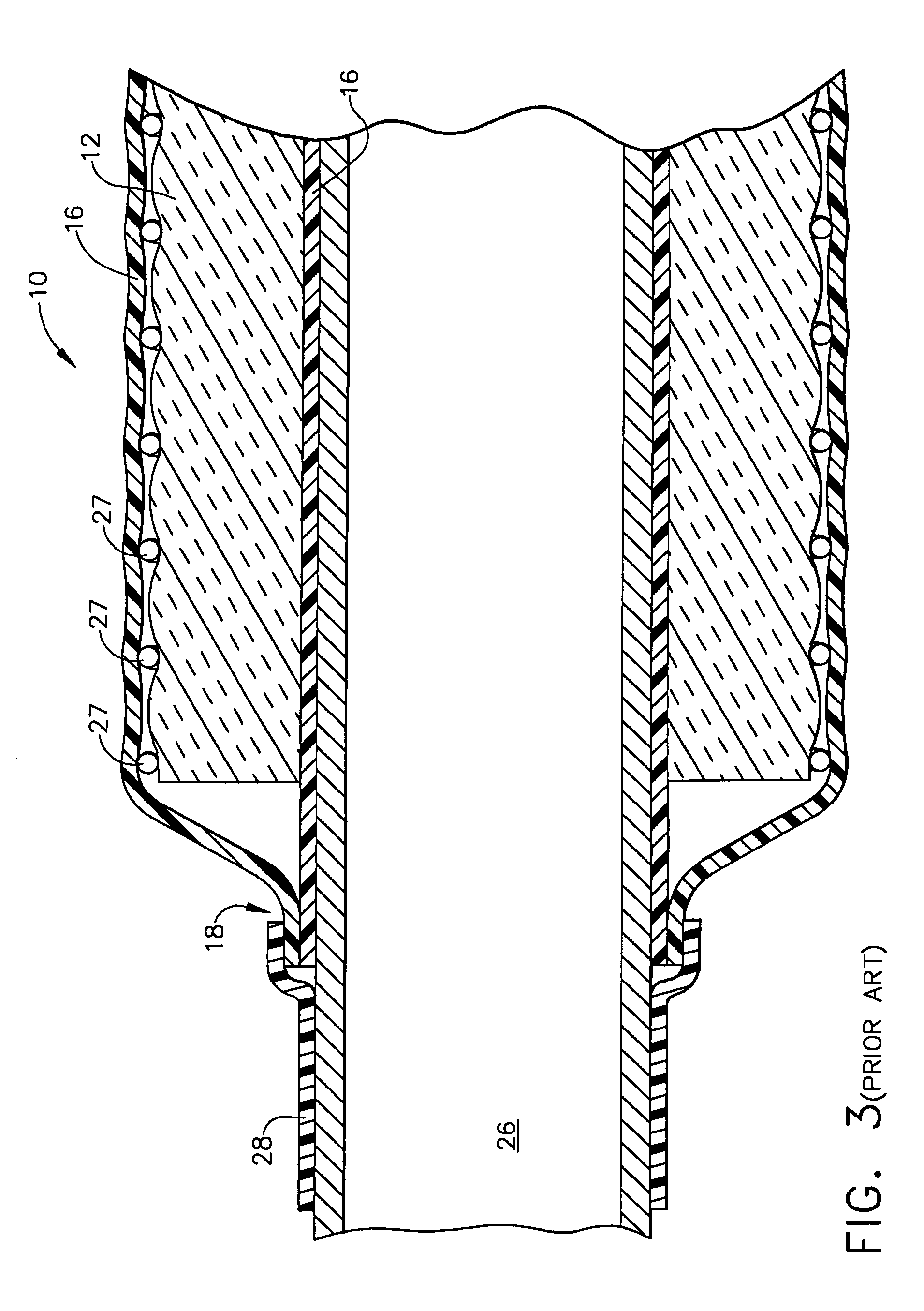
[0045]The following detailed description should be read with reference to the drawings, in which like elements in different drawings are numbered identically. The drawings, which are not necessarily to scale, depict selected embodiments and are not intended to limit the scope of the invention.

[0046]For purposes of illustration, the below discussion will focus on the use of insulation blankets in aircraft but it should be understood by those skilled in the art that the various embodiments of insulation blankets according to the invention can be utilized in a variety of applications, including but not limited to homes, buildings and other structures, piping and duct work, aircraft, watercraft and the like.

[0047]As previously noted, insulation is typically installed to aircraft interior surface structures, subcomponents and subsystems in order to protect occupants, cargo, and equipment, and to piping and duct work that is part of environmental control systems and water and waste system...


PUM

PropertyMeasurementUnit
perimeteraaaaaaaaaa
heightaaaaaaaaaa
thermalaaaaaaaaaa

Abstract

Modularized insulation blanket for thermal and / or acoustical insulation. The modularized insulation blanket has a cover formed of a distal layer and proximal layer in sealed mated relationship. The distal and proximal layers are sealed along longitudinal and latitudinal heat-sealed seams that define a plurality of modules. The heat-sealed seam may be creased so as to be foldable and / or perforated to provide a tear line. Within the modules are batting blocks. The blankets may be attached to surface structures such as the interior skin surface of an aircraft fuselage, pipes or other structures with retention systems. The blankets may be formed in an apparatus including a platen, heat seal rollers or heating sealing mechanisms, and edge sealers.

Description

FIELD OF THE INVENTION[0001]The present invention relates to modular thermal and / or acoustical insulation and retention systems for universal structural applications, methods of making the systems and equipment utilized in the methods. Further, the present invention relates to aircraft fuselages and other structures incorporating the insulation and retention systems.BACKGROUND OF THE INVENTION[0002]Insulation and insulation systems may be utilized to provide thermal and / or acoustical insulation in a variety of applications for homes, buildings and other structures, piping and duct work, aircraft, watercraft and the like. In aircraft, insulation is typically installed to aircraft interior surface structures, subcomponents and subsystems in order to protect occupants, cargo, and equipment, as well as the aircraft structural components from thermal and acoustic extremes and adverse environmental conditions and noise associated with engine operation, mechanical vibration and high veloci...

Claims


Application Information

Patent Timeline
Patent Type & Authority Patents(United States)
IPC IPC(8): B64C1/10B32B1/04B32B3/22E04B1/90
CPCB32B3/22E04B1/90Y10T428/234Y10T428/237Y10T428/233B64C1/40B32B17/10B32B2307/304B32B2307/102B32B27/36B32B27/40B32B27/285B32B27/281B32B3/18B32B18/00B32B27/12B32B37/06B32B19/045B32B2315/085B32B2315/14B32B2315/02B32B37/0076B32B27/304
Inventor MOVSESIAN, SAMIPATEL, JAYANT DAHYABHAIWORKMAN, TEDDERAMO, MARC A.
Owner THE BOEING CO
Why Eureka
Try Eureka