Vertical axis wind turbine

a wind turbine and vertical axis technology, applied in the direction of non-positive displacement fluid engine, liquid fuel engine components, hydro energy generation, etc., can solve the problems of low world reserves of coal, oil and natural gas, less and less favored, etc., to reduce the drag on the prime mover, the effect of reducing the drag

Inactive Publication Date: 2006-08-01
US ISIDRO U
View PDF21 Cites 60 Cited by
  • Summary
  • Abstract
  • Description
  • Claims
  • Application Information

AI Technical Summary

Benefits of technology

[0012]Thus, in preferred embodiments, impingement of a blade by the fluid when in the first position effects rotation of the shaft As the shaft rotates the blade is oriented such that the flow of fluid moves the blade from the first position to the second position, in which there is lower drag. As the blade moves towards the second position, another blade on another arm moves into the first position whereby water impinging on said blade causes further rotation of the shaft. The blade in the second position, having a lower drag than the blade in the first position, reduces the drag on the prime mover than would otherwise be affected by non-movable blades, and hence, effects increased torque output of the prime mover.

Problems solved by technology

Traditional sources of generating energy such as the combustion of fossil fuels, including coal, natural gas and oil, are becoming less and less favored due to their environmental disadvantages.
The combustion of coal, oil or gas generates large quantities of carbon dioxide, oxides of sulfur and nitrogen, and other pollutant gases, which may contribute to global warming, acid rain, air pollution and a number of other environment and health damaging effects.
World reserves of coal, oil and natural gas are also thought to be relatively low, and may run out in the foreseeable future.
Unfortunately, the use of radioactive materials means that environmentally safe methods of disposal of waste are difficult to achieve.
There have been many occurrences of radioactive waste leaking from these containers and damaging the local environment.
The damage caused by radioactive waste may be irreversible and the radiation generated by the waste may last decades.
However, this configuration of fixed blades means that trailing blades are not optimally configured to reduce drag and thus prevent the maximum amount of linear to rotational motion available to generators.
Thus the optimal conversion of linear to rotational motion may not be achieved using these known systems, and consequently, optimal energy generation is not possible.

Method used


Image

  • Vertical axis wind turbine
  • Vertical axis wind turbine
  • Vertical axis wind turbine

Examples


second embodiment

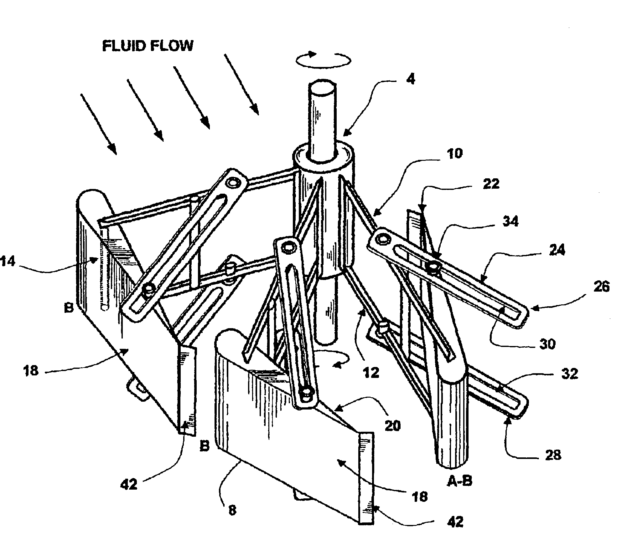
[0054]Referring now to FIGS. 3 and 4, the prime mover 2 of the invention includes all the elements of the embodiment described for FIGS. 1 and 2, but include means 24 to limit the movement of the blades 8 to between the first and second positions (“A” and “B” respectively) only. The movement limiting means 24 comprises an upper 26 arm and lower 28 arm extending obliquely from each arm 6 of the prime mover 2. The upper arms 26 and lower arms 28 include upper slots 30 and lower slots 32 respectively. The movement limiting means 24 further comprises guide rods 34, which extends through the blades 8 of the prime mover 2 into the upper 30 and lower 32 slots of each movement limiting means 24.

[0055]In use the guide rods 34 cooperate with the upper 30 and lower 32 slots to limit movement of each blade to between the first position “A” and the second position “B” as shown in FIG. 4. In the first position “A” the guide rod is located at the proximal end of the upper 30 and lower 32 slots of ...

fourth embodiment

[0063]The mode of the operation of the fourth embodiment is substantially identical to that described on the embodiment of FIGS. 1 and 2.

[0064]Referring now to FIG. 7, in a fifth embodiment of the prime mover 2 of the invention, each arm 6 comprises two blades 8, which are superposed. Each arm 6 comprises upper 38 and lower 40 retention bars, to retain each of the blade. Each blade 8 comprises its own pivot 14, but in another embodiment (not shown) there may be a single pivot running through both blades. The mode of operation of the fifth embodiment is substantially identical to that described for the embodiment of FIGS. 1 and 2.

sixth embodiment

[0065]Referring now to FIGS. 8 and 9, the prime mover 2 of the invention includes all the elements of the embodiment described for FIGS. 3 and 4, but now include a trim tab 42 attached to the blade 8 trailing edge or tip 22 of each blade 8 to provide fine tuning adjustment to increase blade efficiency. The trim tab 42, either welded, riveted, or a plate integral part of blade 8, partly spanning or extending fully to cover the whole length along the blade 8 trailing edge or tip 22.

[0066]In use, the trim tab 42 alters the blade 8 attitude with reference to the fluid flow every time blades 8 guide rods 34 are not setting at the distal or proximal ends of the movement limiting means 24, thus increases blade efficiency.

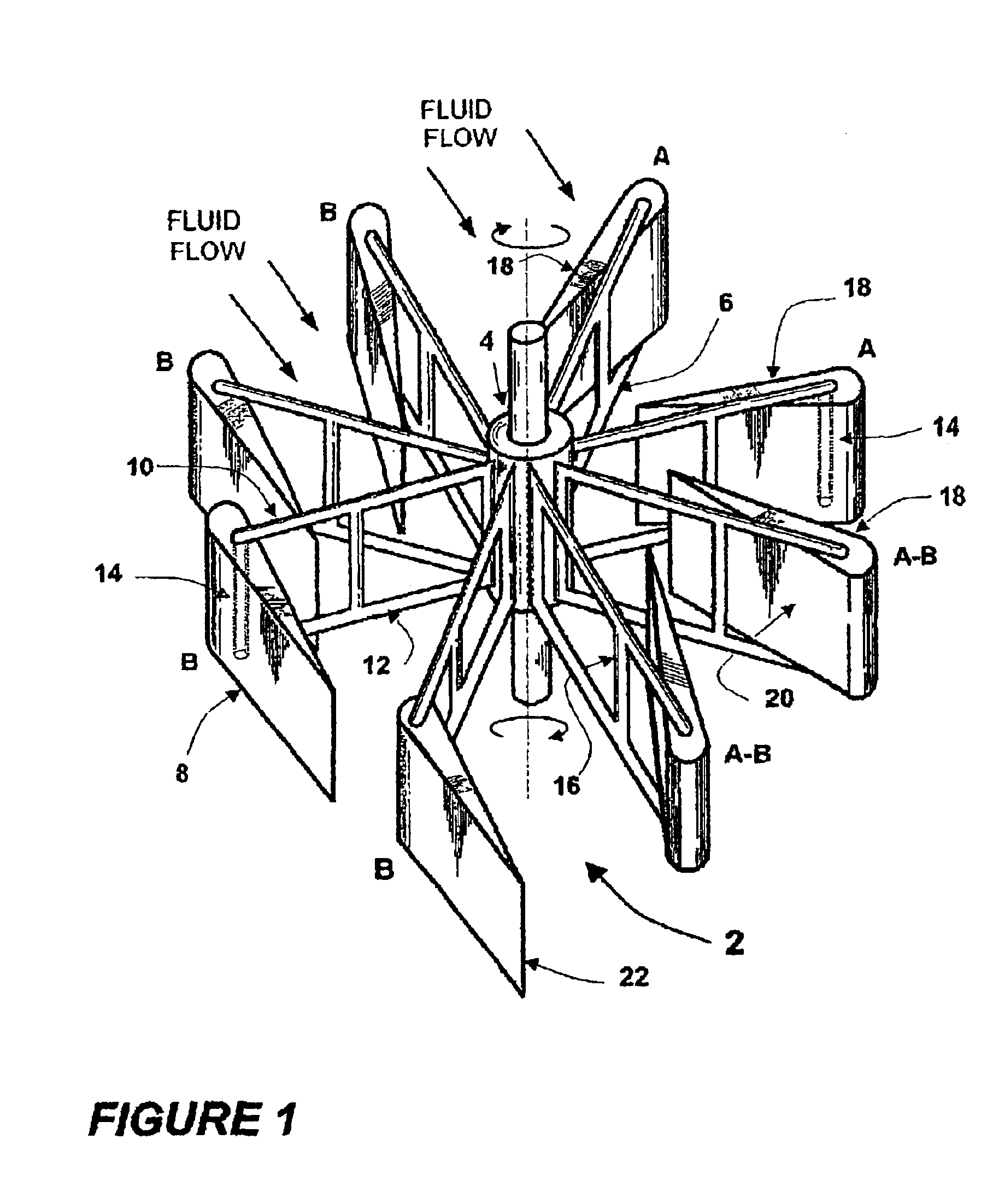
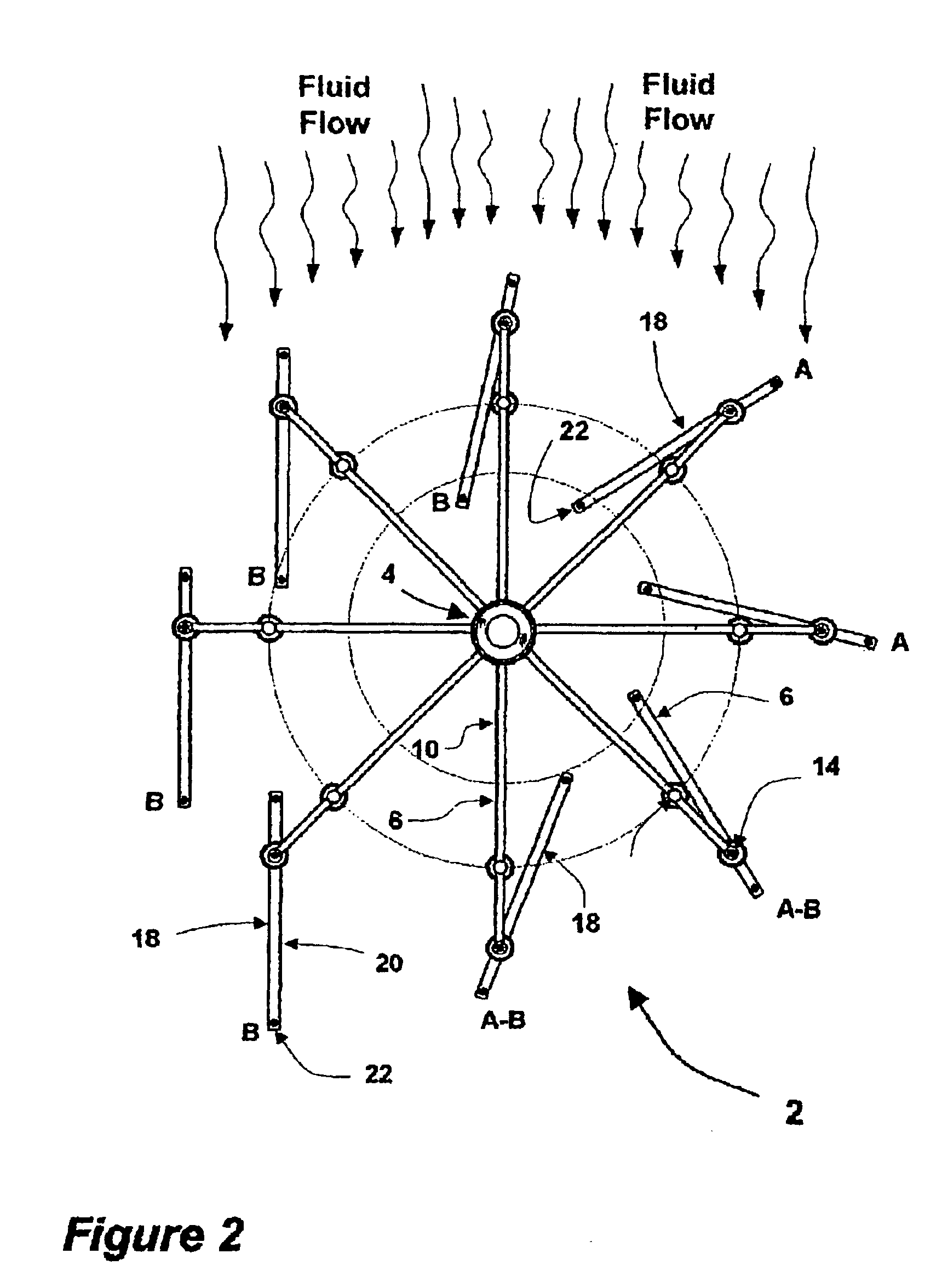
[0067]Thus, in each of the embodiments described above, movement of the blades 8 from the first position ‘A’ to the second position ‘B’ moves the blades from a higher drag orientation to a much lower drag orientation in the fluid, to provide for a reduction in the energy l...


PUM


Abstract

The present invention provides a prime mover (2) for harnessing energy from a flow of fluid, the prime mover (2) comprising a shaft (4) having a rotational axis, arranged to be rotatably mounted to a substructure, the shaft (4) comprising at leas one arm (6) extending radially from the shaft (4), the or each arm (6) comprising at least one blade (8) wherein the or each blade (8) is oriented such that flow action on the blade (8) effects rotation of the shaft (4), characterized in that the or each blade (8) is movably mounted on an arm (6) and wherein each blade (8) is movable from a first position, having a first drag, to a second position, having a second drag, wherein the first drag is higher than the second drag. The prime mover (2) of the invention provides substantially reduced drag in a flow of fluid, and an increased torque output, compared to prior art prime movers.

Description

TECHNICAL FIELD OF THE INVENTION[0001]This invention relates to a prime mover, and in particular to a prime mover which harnesses energy from a flow of fluid. The invention also extends to a method of generating energy and an energy-generating device.BACKGROUND OF THE INVENTION[0002]Renewable and non-polluting sources of energy are currently in high demand. Traditional sources of generating energy such as the combustion of fossil fuels, including coal, natural gas and oil, are becoming less and less favored due to their environmental disadvantages. The combustion of coal, oil or gas generates large quantities of carbon dioxide, oxides of sulfur and nitrogen, and other pollutant gases, which may contribute to global warming, acid rain, air pollution and a number of other environment and health damaging effects. World reserves of coal, oil and natural gas are also thought to be relatively low, and may run out in the foreseeable future.[0003]Other sources of energy include nuclear fiss...

Claims


Application Information

Patent Timeline
Patent Type & Authority Patents(United States)
IPC IPC(8): F03D1/06F03B3/12F03B17/06F03D3/00F03D3/06F03D11/04
CPCF03B17/065F03D3/005F03D3/061F03D3/067F05B2210/16Y02E10/74F05B2250/70F05B2260/72Y02E10/28Y02E10/721F05B2240/301Y02E10/72Y02E10/30F03D3/06Y02E10/20
Inventor URSUA, ISIDRO U.
Owner US ISIDRO U
Why Eureka
Try Eureka