
Low leakage monotonic CMOS logic

a monotonic, low leakage technology, applied in the direction of logic circuit coupling/interface arrangement, power consumption reduction, pulse technique, etc., can solve the problem of reducing the operating time of the device, and achieve the effect of reducing the leakage curren

Active Publication Date: 2006-08-01
MARVELL ASIA PTE LTD
View PDF4 Cites 7 Cited by
  • Summary
  • Abstract
  • Description
  • Claims
  • Application Information

AI Technical Summary

Benefits of technology

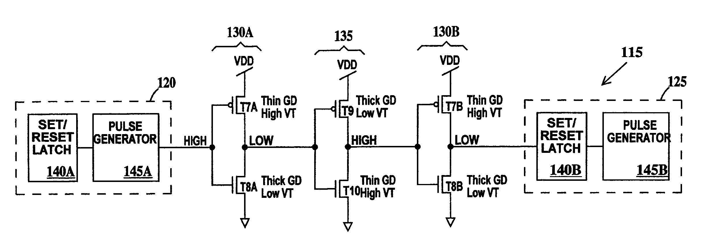
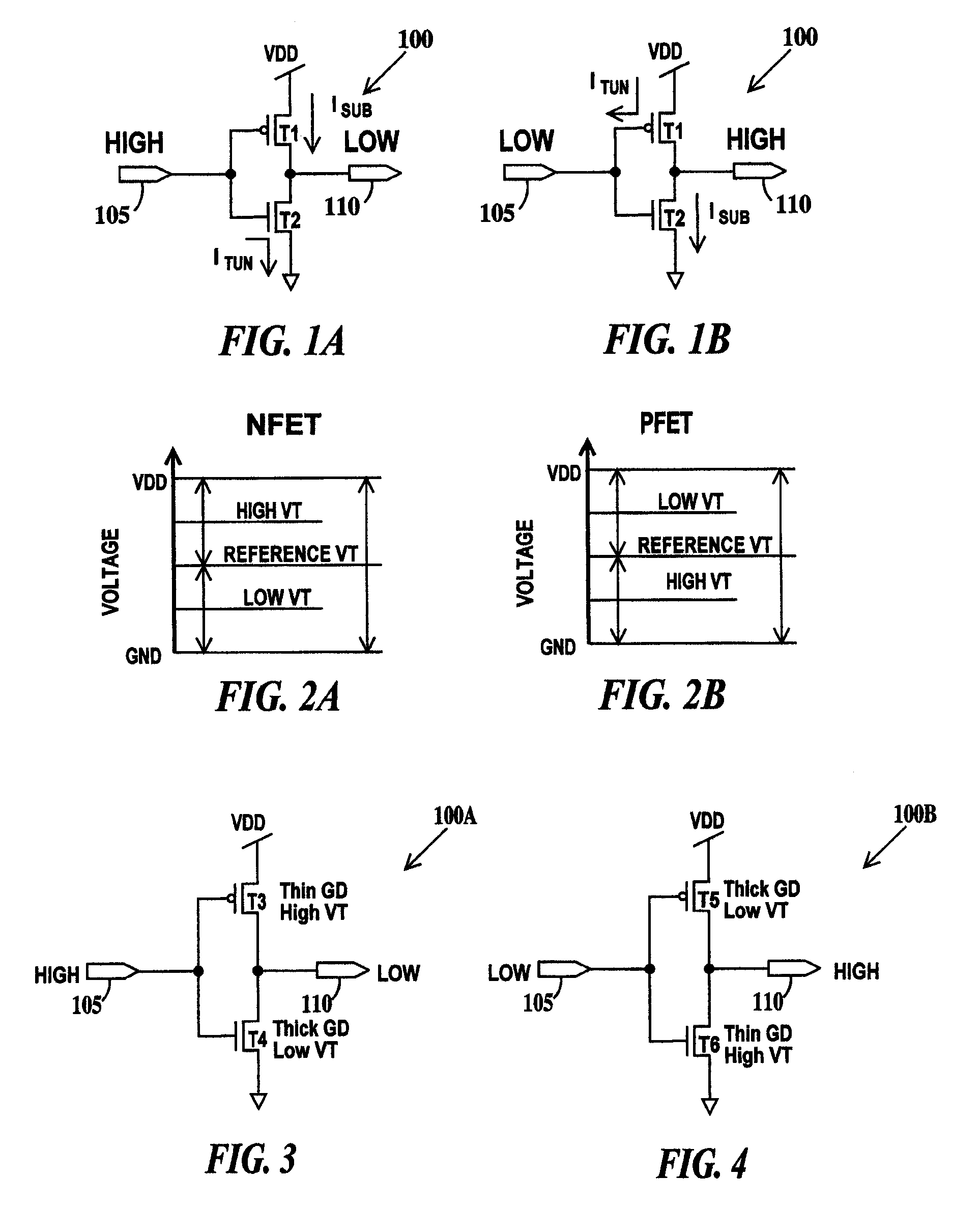
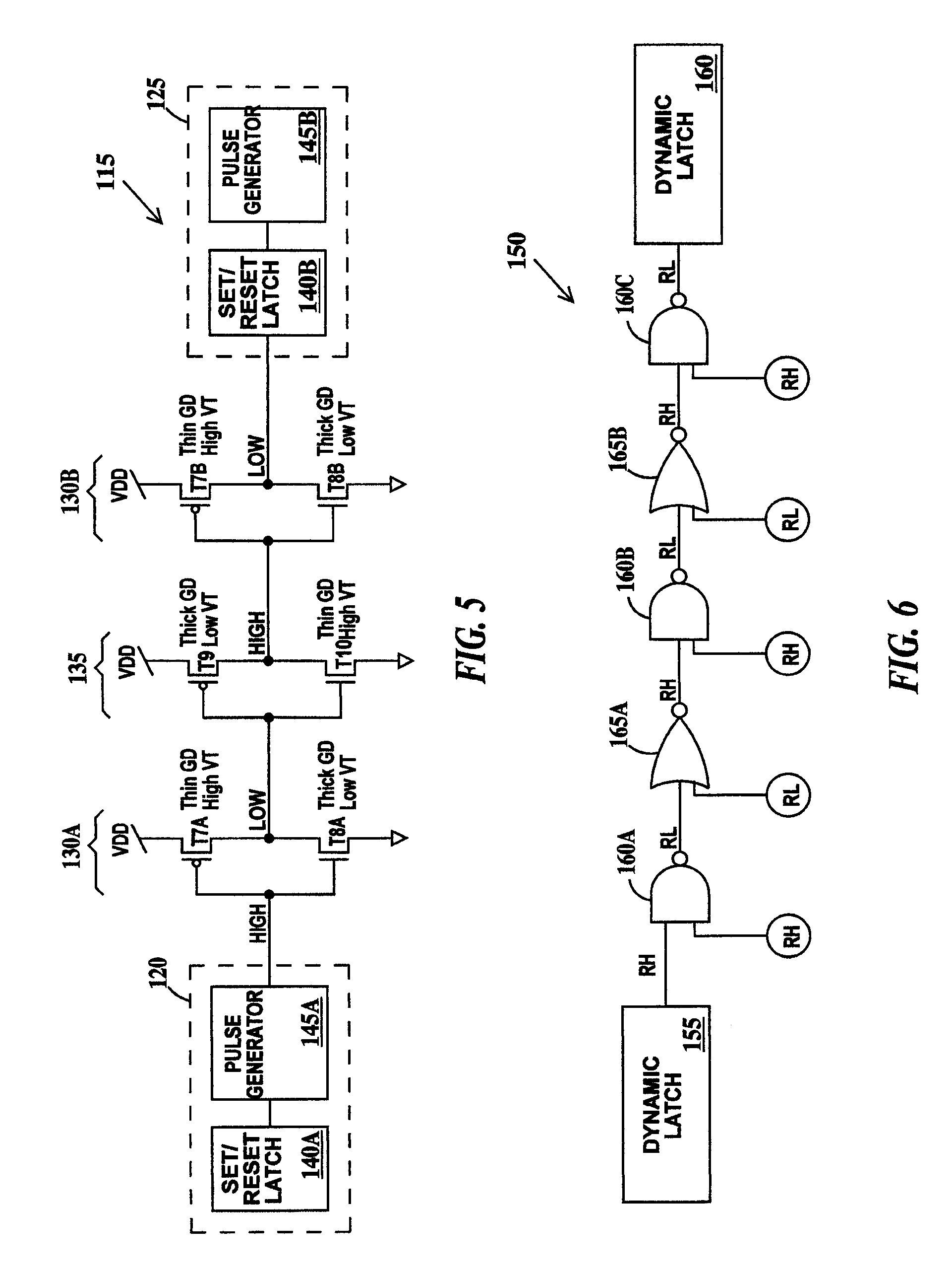
[0006]A second aspect of the present invention is a method of reducing leakage current in a circuit, comprising: specifying a reference PFET having its threshold voltage and its gate dielectric thickness and a reference NFET having its threshold voltage and its gate dielectric thickness; providing the circuit, the circuit having one or more logic stages; connecting at least one of the logic stages to an input having a predominantly high input state or having a predominantly low input state; wherein the logic stages connected to the input having the predominantly high input state, comprise one or more thin gate dielectric and high threshold voltage PFETs with respect to the reference PFET and one or more thick gate dielectric and low threshold voltage NFETs with respect to the reference NFET; and wherein the logic stages connected to the input having the predominantly low input state, comprise one or more thick gate dielectric and low threshold voltage PFETs with respect to the reference PFET and one or more thin gate dielectric and high threshold voltage NFETs with respect to the reference NFET.

Problems solved by technology

High leakage current can result in reduced device operating time in the case of battery operated devices.

Method used


Image

  • Low leakage monotonic CMOS logic
  • Low leakage monotonic CMOS logic
  • Low leakage monotonic CMOS logic

Examples


Embodiment Construction

[0023]For the purposes of the present invention the term “high” on an input, output or circuit node means a logical one on the input, output or circuit node and the term “low” means a logical zero on the input, output or circuit node. A logical one also corresponds to a voltage level sufficient to turn on an N-channel field effect transistor (NFET) and is often also referred to as VDD. A logical zero corresponds to a voltage level sufficient to turn on a P-channel field effect transistor (PFET) and is often also referred to as GND. These usages of high and low should not be confused with the terms high and low threshold voltage (VT), which are defined infra. VDD and GND can also be considered as first and second rails of a power supply.

[0024]FIGS. 1A and 1B are exemplary schematic circuit diagrams illustrating sources of leakage current in CMOS logic circuits in general and monotonic circuits in particular. A monotonic circuit is defined as a circuit that requires no clock signal fo...


PUM


Abstract

A low leakage monotonic CMOS logic circuit and a method, a method of design and a system for designing such circuits. The circuit, including: one or more logic stages, at least one of the logic stages having a predominantly high input state or having a predominantly low input state; wherein the logic stages having the predominantly high input state, comprise one or more thin gate dielectric and high threshold voltage PFETs with respect to a reference PFET and one or more thick gate dielectric and low threshold voltage NFETs with respect to a reference NFET; and wherein the logic stages having the predominantly low input state, comprise one or more thick gate dielectric and low threshold voltage PFETs with respect to the reference PFET and one or more thin gate dielectric and high threshold voltage NFETs with respect to the reference NFET.

Description

BACKGROUND OF INVENTION[0001]1. Field of the Invention[0002]The present invention relates to the field of digital circuits; more specifically, it relates to monotonic complimentary metal-oxide-silicon (CMOS) digital circuits and a method of controlling leakage current in monotonic CMOS logic circuits.[0003]2. Background of the Invention[0004]An increasing concern in advanced digital circuit design is the control of leakage current, especially when the digital logic circuit is in the precharge or standby state, which is often the predominant state in terms of the amount of time that the circuit is in that state compared to other states of the circuit. High leakage current can result in reduced device operating time in the case of battery operated devices. Therefore, there is a need for reduced leakage current circuits and method for reducing leakage current in digital CMOS logic circuits.SUMMARY OF INVENTION[0005]A first aspect of the present invention is an integrated circuit, compr...

Claims


Application Information

Patent Timeline
Patent Type & Authority Patents(United States)
IPC IPC(8): H03K19/0175
CPCG06F17/505H03K19/0948H03K19/0016G06F30/327
Inventor BERNSTEIN, KERRYROHRER, NORMAN J.
Owner MARVELL ASIA PTE LTD
Learn More