Ultra wide band base band receiver

a receiver and base band technology, applied in the direction of multiple modulation transmitter/receiver arrangement, synchronisation signal speed/phase control, high-level techniques, etc., can solve the problems of increasing data interference, poor signal reception, and using conventional narrowband modulated carrier frequencies, so as to reduce the cost and facilitate the fabrication of the receiver

Inactive Publication Date: 2006-08-08
INTELLECTUAL VENTURES HLDG 73
View PDF157 Cites 43 Cited by
  • Summary
  • Abstract
  • Description
  • Claims
  • Application Information

AI Technical Summary

Benefits of technology

[0020]The present invention is a base band receiver system and method that receives and demodulates data transmitted, without a carrier frequency, as series of ultra-short, spread spectrum modulated electromagnetic pulses. The electromagnetic pulses each include a digital signal representative of a transmitted value. The receiver system advantageously converts the ultra-short, spread spectrum pulses directly to data without going through intermediate frequency (IF) down conversion. The elimination of IF down conversion allows reduced cost and easier fabrication of the receiver as a single chip device.
[0022]The receiver system and method is capable of receiving signals using different modulation techniques and having different pulse repetition frequencies. By way of example and not of limitation, the different modulation techniques include on-off keying and pulse amplitude modulation. The receiver includes a decoder which takes values from an analog digital converter and converts these values to signals. For different modulation methods such as pulse amplitude modulation or on-off keying, the decoder is capable of detecting different threshold levels which identify the particular modulation method. This allows system transceivers to negotiate a link in bandwidth that depends on environmental issues such as bit error rate, signal to noise ratio and delay spread from receiving the signals. Additionally the reception of these signals allows different transceiver performance levels to operate on the same network. Thereby allowing backward compatibility to designed into the system and allowing newer devices to communicate with older devices using lower symbol frequency or fewer bits per symbol. The synchronization control for the various modulation methods is perform at the Medium Access Control (MAC) layer. To perform synchronization the MAC protocol communicates to an appropriate slot allocation unit the desired modulation scheme for the particular slot.

Problems solved by technology

There are important disadvantages associated with using conventional narrowband modulated carrier frequencies.
Particularly, in multipath environments such as inside rooms and buildings, data communication degrades because of multipath propagation or fading and can result in poor signal reception.
Further, the rapidly increasing use of wireless consumer products has “crowded the airwaves” and will result in increasing interference with reception of data.
Still further, narrow band modulated carriers rely on use of relatively expensive components such as high-Q filters, precise local high-frequency oscillators, and power amplifiers.
Spread-spectrum signals for digital communications were originally developed and used for military communications either to provide resistance to jamming or to hide the signal by transmitting the signal at low power and, thus, make it difficult for an unintended listener to detect its presence in noise.

Method used


Image

  • Ultra wide band base band receiver
  • Ultra wide band base band receiver
  • Ultra wide band base band receiver

Examples


Embodiment Construction

[0036]Those of ordinary skill in the art will realize that the following description of the present invention is illustrative only and not in any way limiting. Other embodiments of the invention will readily suggest themselves to such skilled persons.

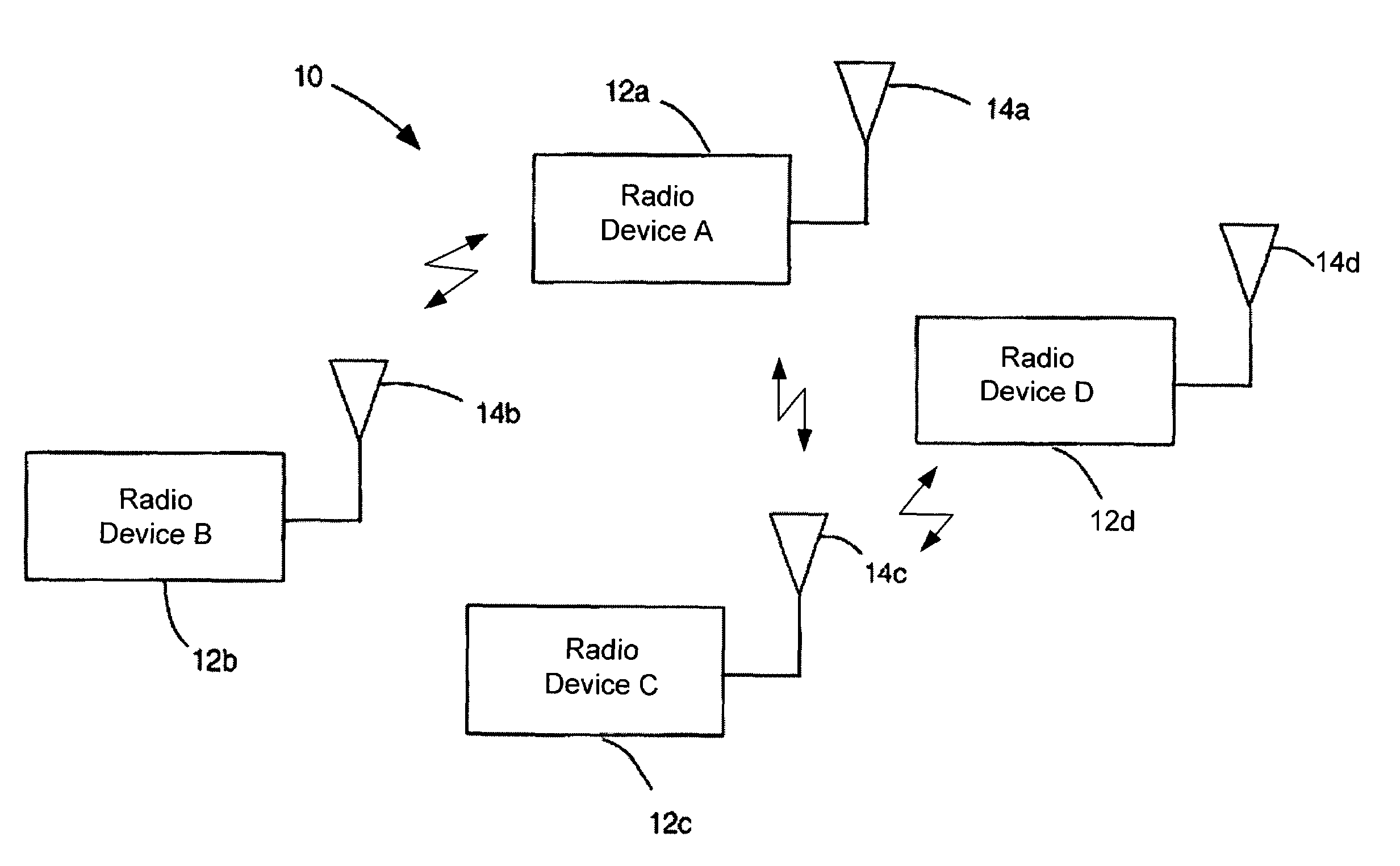
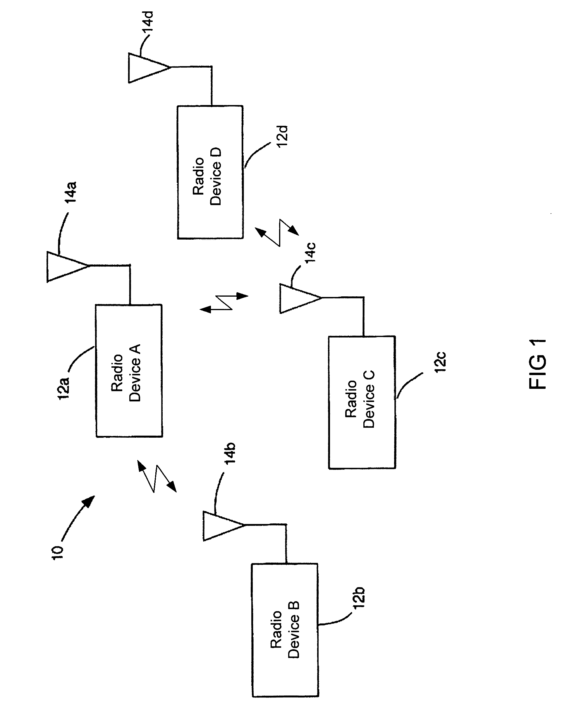
[0037]The present invention provides a Time Division Multiple Access (TDMA) system and method that allows sharing a wireless medium which can identify and operate in a variable bit rate environment. The present invention provides a system and method capable of supporting devices with vastly different bandwidth requirements. Some devices, such as a televisions, require high bandwidth data communication. The higher cost associated with a television allows for the design of a television having high data rate modulation techniques. Other device such as home thermostats have lower bandwidth requirements and require simpler modulation techniques for lower cost connectivity.

[0038]The present invention operates within a network which allows dev...


PUM


Abstract

The present invention is a receiver having a radio frequency (RF) front end, a pulse detector operatively coupled to the RF front end, and a data recovery unit operatively coupled to the pulse detector. The data recovery unit is configured to receive spread spectrum RF signals having different pulse repetition frequencies and using different modulation techniques. The receiver may operate in conjunction with a transmitter as a transceiver. The receiver may also operate in a networked environment in which a network of transceiver node devices comprise a first slave transceiver having a receiver configured to receive spread spectrum signals, and a second slave transceiver configured to communicate with the first slave transceiver. Additionally, a master transceiver is in communication with the first slave transceiver and the second slave transceiver. The master transceiver is configured to manage data transmissions and synchronization between the first slave transceiver and the second slave transceiver.

Description

[0001]The present application is a continuation-in-part patent application of patent application Ser. No. 09 / 433,520 filed Nov. 3, 1999 now U.S. Pat. No. 6,275,544 titled “Baseband Receiver Apparatus and Method”.BACKGROUND OF THE INVENTION[0002]1. Field of the Invention[0003]This invention pertains generally to systems and methods for a wireless data receiver. More particularly, the invention relates to an ultra wideband receiver for receiving base band signals.[0004]2. Description of the Background Art[0005]Wireless communication increasingly relies on the transmission of data in digital formats. Typically, a data stream is modulated onto a carrier frequency, and the modulated carrier signal is transmitted over a communications channel from a transmitter to a receiver. Generally, these communication systems use conventional narrow band modulated carriers for wireless network communication.[0006]There are important disadvantages associated with using conventional narrowband modulate...

Claims


Application Information

Patent Timeline
Patent Type & Authority Patents(United States)
IPC IPC(8): H04L7/00H04B1/69H04L1/00H04L7/033H04L7/04H04L27/00H04L27/06
CPCH04B1/7183H04L1/0003H04L7/042H04L27/0012H04L27/066H04L27/0008H04B1/71632H04B2001/6908H04L7/033Y02B60/31H04L2027/003H04L2027/0036H04L2027/0067H04L2027/0095Y02D30/50
Inventor AIELLO, ROBERTOSPARRELL, CARLTONROGERSON, GERALD
Owner INTELLECTUAL VENTURES HLDG 73
Why Eureka
Try Eureka