
Low equivalent weight ionomer

Inactive Publication Date: 2006-08-22
WL GORE & ASSOC INC
View PDF35 Cites 54 Cited by
  • Summary
  • Abstract
  • Description
  • Claims
  • Application Information

AI Technical Summary

Benefits of technology

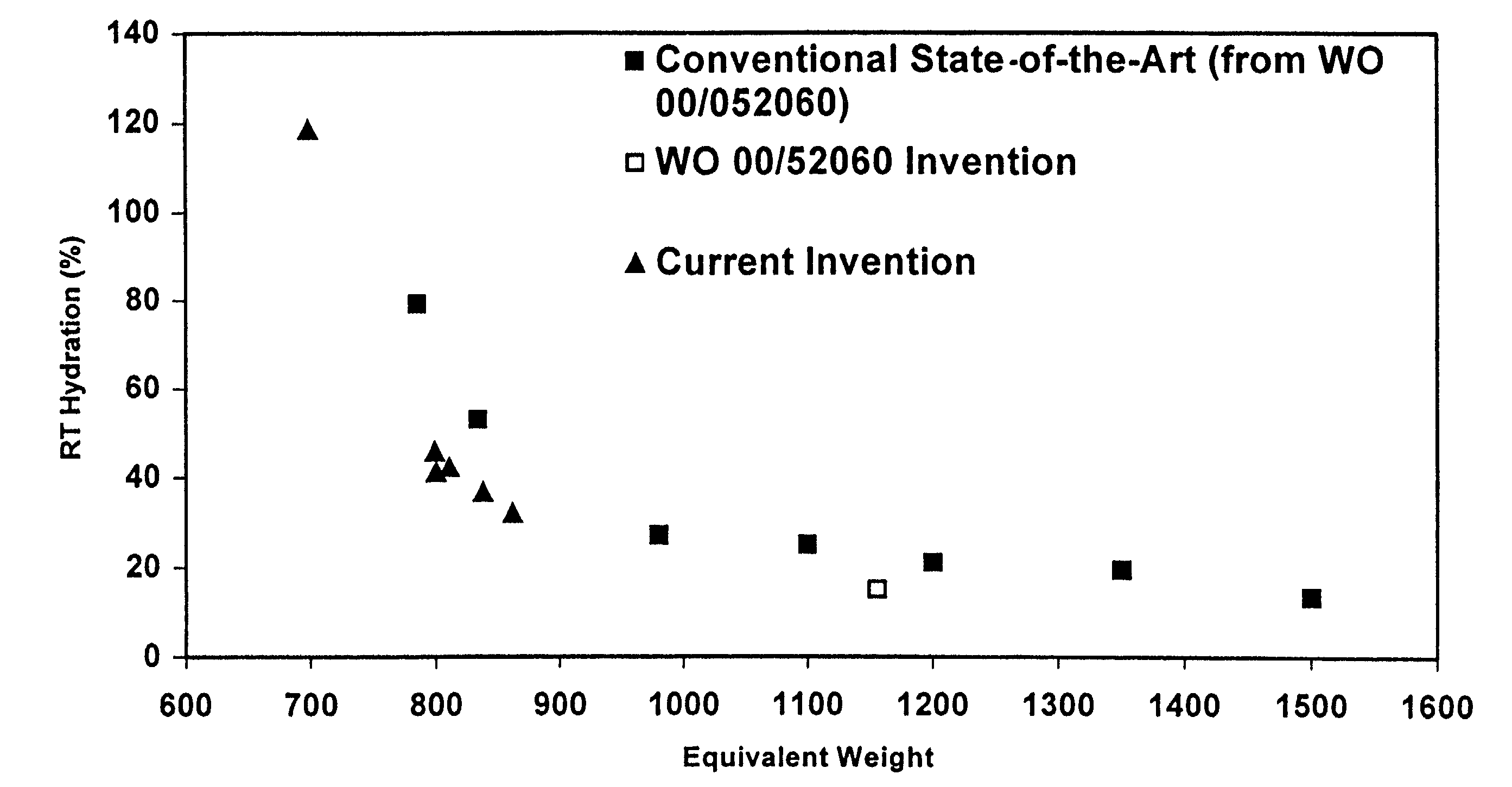
[0017]The present invention is an ionomer and a process for forming the ionomer such that the ionomer has (1) low equivalent weight (below 950, preferably between 625 and 850, and most preferably between 675 and 800) and (2) high conductivity (greater than 0.13 S / cm). In another embodiment, the invention is an ionomer having (1) low equivalent weight (below 950, preferably between 625 and 850, and most preferably between 675 and 800) and (2) acceptably low hydration (less than about 120 weight percent). These ionomers are capable of being processed into thin film and are extremely well-suited for low humidity or high temperature fuel cell applications.

Problems solved by technology

Lowering the equivalent weight has previously not been a practical approach to making useful membranes.
But there is a limit to the amount of water or solvent such fluoropolymer membranes can contain.
If too much water is present, the film may lose much of its physical integrity, becoming gel-like with little or no rigidity.
Furthermore, even if the films were stable, too high a hydration would tend to dilute the number of ions present for conduction, thereby lowering the ionic conductivity.
Thus, one would like to decrease the equivalent weight of these fluoropolymers to increase their conductivity, but heretofore could not practically do so because the degree of hydration and / or water solubility was too high to form practical membranes.
Although each of these approaches may offer some improvement over the a monolithic single layer fluoropolymer membrane, they all involve the use of rather complex, composite, multilayer structures that can be difficult and / or expensive to process.
This approach is particularly desirable for use in coating processes (for example, as described in U.S. Pat. Nos. 4,661,411 and 5,718,947) but still suffers limitations for use as fluoropolymer ionomer membranes.
In particular, these polymers can still be difficult to form into acceptably thin, strong membranes from solution.
Thus, these films might be expected to be relatively weak because of the high hydration.
A common problem associated with such fuel cells is that contaminants such as carbon monoxide tend to poison the catalysts used in the MEA.
These contaminants can interfere with the flow of ions between the electrodes and thus degrade the performance of the fuel cell.
The problem with running at high temperatures, however, is that it vaporizes liquid water within the fuel cell, and in so doing, tends to reduce the degree of hydration in the membrane.
As described above, decreasing the hydration lowers the ionic conductivity, thereby reducing the efficiency of ion transport through the membrane and adversely affecting fuel cell operation.
However, as the temperature gets close to, or above, the boiling point of water this approach becomes difficult and inefficient.
These factors would counsel against their use in environments where water is produced, e.g. hydrogen-oxygen fuel cells, because these polymers tend to become physically unstable in these environments.
Additionally, new applications heretofore not practical may become possible with this new, unique set of characteristics.

Method used


Image

  • Low equivalent weight ionomer
  • Low equivalent weight ionomer
  • Low equivalent weight ionomer

Examples


example 1

[0055]An aqueous mini-emulsion was prepared by pre-mixing and homogenization of a mixture containing 1650 grams of deionized water, and 50 grams of 20% by weight of ammonium perfluoro octanoate (ammonium salt of perfluoro octanoic acid) aqueous solution, and 194 grams of 82.5% by weight of CF2═CF—O—CF 2CF(CF3)—O—CF2CF2—SO2F monomer and 17.5% by weight of Fluorinert® FC-77 (a perfluorinated hydrocarbon, manufactured by 3M). A mini-emulsion was formed using the homogenizing module of a microfluidizer. An air motor using compressed air of about 40 psi sent the mixture through the homogenizing module. The whole mixture was sent through the homogenizing module six times. The final mixture was a translucent aqueous mini-emulsion of very light blue color. The aqueous mini-emulsion was then added to a 4-liter reactor. The reactor was evacuated three times and purged each time with tetrafluoroethylene gas. The oxygen content of the aqueous solution was about 20 ppm immediately prior to admit...

examples 2 – 5

EXAMPLES 2–5

[0057]An aqueous mini-emulsion of polymer was prepared using a procedure similar to that of Example 1, but the polymerization was performed in a 30 liter reactor. Several reactions were performed at different reaction times and reactions pressures as shown in Table 1. In particular, an aqueous emulsion was prepared by pre-mixing 14,900 grams of deionized water, and 375 grams of 20% by weight of ammonium perfluoro octanoate (ammonium salt of perfluoro octanoic acid) aqueous solution, and 1200 grams of CF2═CF—O—CF2CF(CF3)—O—CF2CF2—SO2F monomer and 300 grams of Fluorinert® FC-77 (a perfluorinated hydrocarbon, manufactured by 3M). This mixture was homogenized to form a mini-emulsion using the same procedure described in Example 1. The aqueous mini-emulsion was then added to a 30 liter pressure reactor. The reactor was evacuated three times and purged each time with tetrafluoroethylene gas. The oxygen content of the aqueous solution was about 20 ppm immediately prior to admit...


PUM

PropertyMeasurementUnit
Fractionaaaaaaaaaa
Fractionaaaaaaaaaa
Fractionaaaaaaaaaa

Abstract

An ionomer and a process for forming the ionomer such that the ionomer has (1) low equivalent weight (below 950, preferably between 625 and 850, and most preferably between 675 and 800) and (2) high conductivity (greater than 0.13 S / cm). In another embodiment, the invention is an ionomer having (1) low equivalent weight (below 950, preferably between 625 and 850, and most preferably between 675 and 800) and (2) acceptably low hydration (less than about 120 weight percent). These ionomers are capable of being processed into thin film and are extremely well-suited for low humidity or high temperature fuel cell applications.

Description

FIELD OF THE INVENTION[0001]This invention relates to fluorinated ionomers, and specifically to fluorinated ionomers of low equivalent weight that have relatively low hydration that can be processed into thin films. The fluorinated ionomers are preferably perfluorinated compounds suitable for applications where reasonably high ionic conductivity in low humidity environments is desirable. One such application is in solid polymer electrolyte fuel cells.BACKGROUND OF THE INVENTION[0002]Solid polymer ionic membranes or films have been well known in the art for many years. These polymers are typically characterized by high ionic conductivity, i.e., rapid transport of ionic species, for example, protons. Additionally, it is desirable for such ionically conducting polymers to be made in the form of membranes or thin films. In so doing, the resistance to ionic transport, which is a function of the film thickness, can be reduced. Fluoropolymer compositions are particularly desirable for such...

Claims


Application Information

Patent Timeline
IPC IPC(8): C08F16/24C08J5/18C08F214/18C08F216/14C25B9/23H01M4/86H01M8/02H01M8/10
CPCC08F216/1408H01M4/8605H01M8/0291H01M8/1039H01M8/1072H01M8/1025H01M8/1004Y02E60/521H01M2300/0082H01M2300/0094H01M8/0289Y02P70/50Y02E60/50C08F214/18C08F214/26C08J5/22
Inventor WU, HUEY SHENMARTIN, CHARLES W.CHEN, XIN KANG
Owner WL GORE & ASSOC INC
Learn More