
Method and apparatus for measuring temporal response characteristics of digital mirror devices

Active Publication Date: 2006-08-22
TEXAS INSTR INC
View PDF9 Cites 13 Cited by
  • Summary
  • Abstract
  • Description
  • Claims
  • Application Information

AI Technical Summary

Benefits of technology

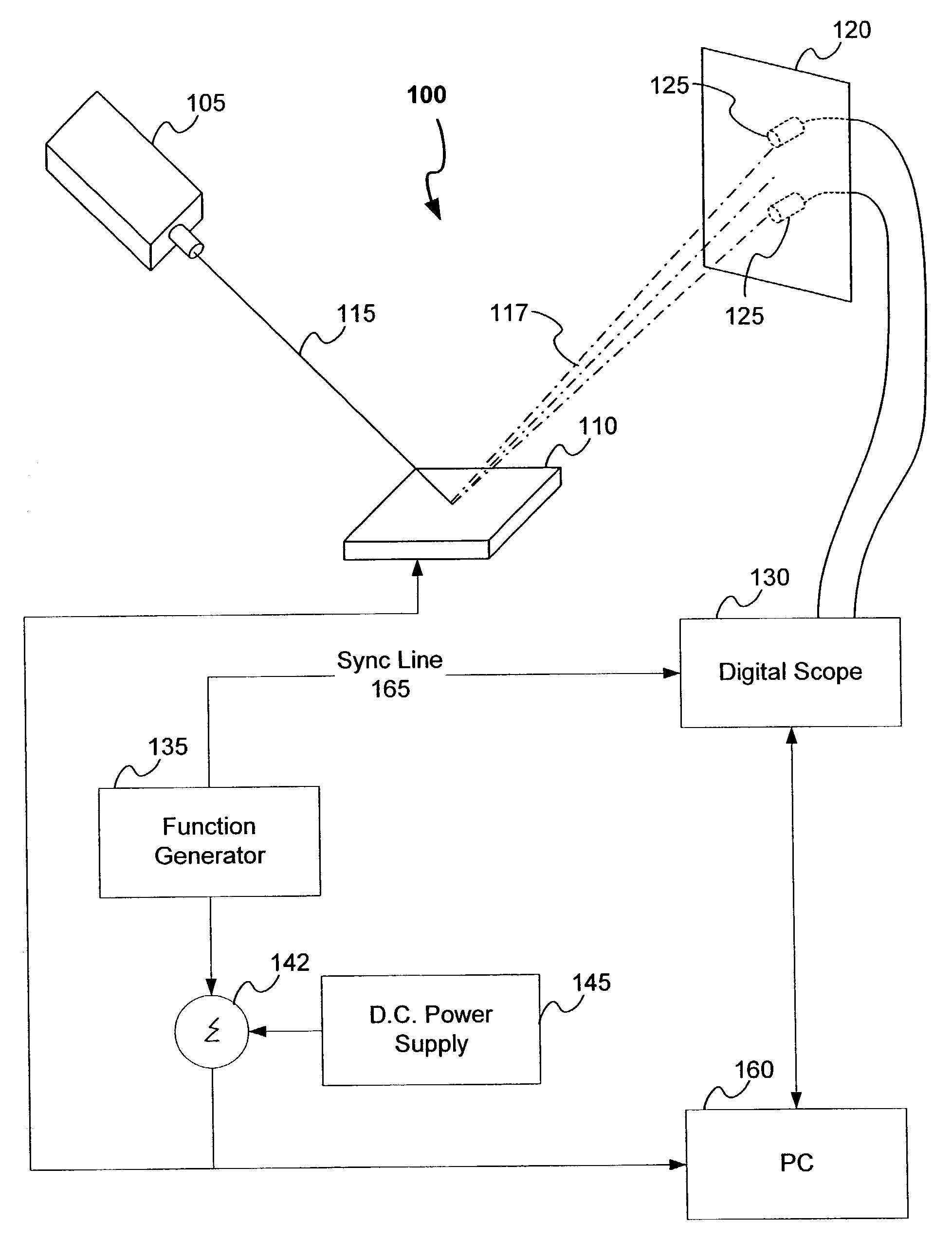
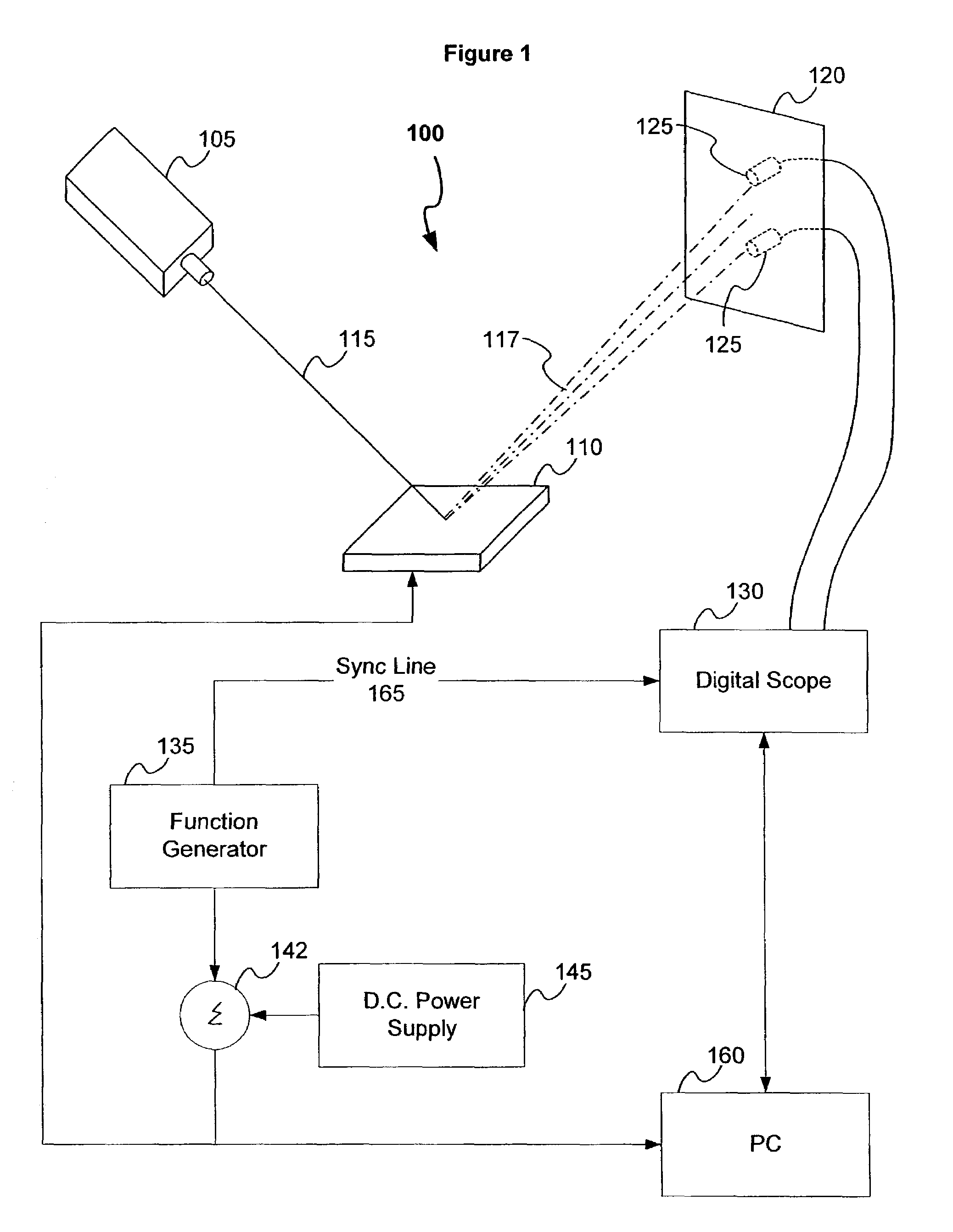
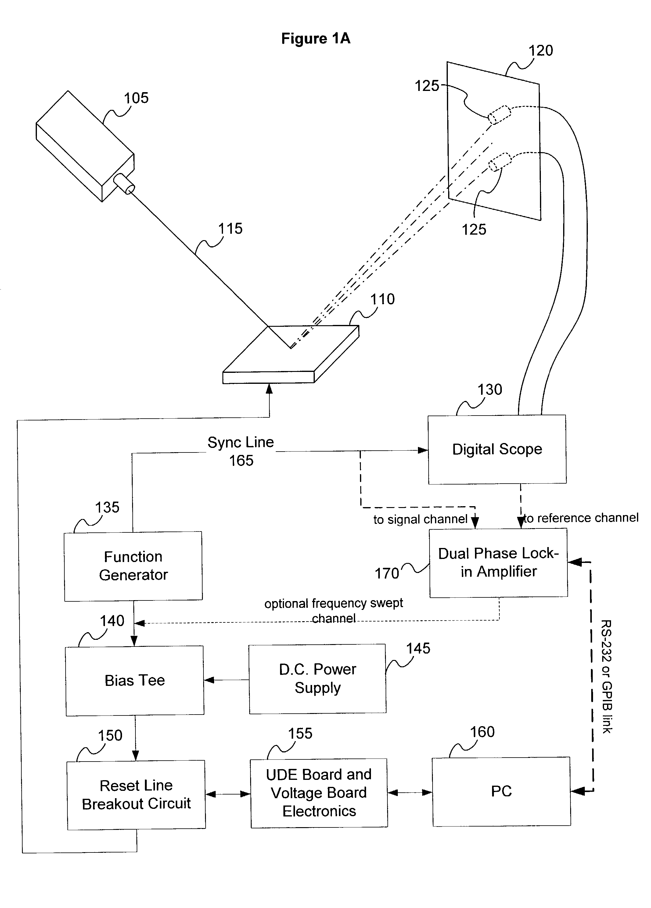
[0009]An improved method and apparatus for performing temporal measurements of the response characteristics of a micromirror array are disclosed in this application. The system utilizes a coherent light source, such as a laser, to illuminate a portion of a micromirror array so that a diffraction pattern is reflected by the micromirror array onto a reflection screen. Diffraction pattern theory dictates that as the micromirrors of the micromirror array are tilted to new angles in unison, the intensity, but not the location, of the spots of the diffraction pattern will change. Photodetectors can therefore be aligned with certain spots in the diffraction pattern so that the intensity of these spots can be accurately measured as the micromirrors are tilted to different angles in unison. In order to perform accurate measurements of the temporal response of the mirrors to various stimuli, a system may be connected to the micromirror array and to the photodetectors to drive the micromirror array with input signals and measure its response characteristics.

Problems solved by technology

These measurement tools have significant drawbacks though.
In particular, the tools are expensive, highly sensitive, and require precise alignment with the micromirror array in order to produce accurate measurements.
Furthermore, these tools can only measure one mirror at a time, thus producing measurement that have a relatively low signal to noise ratio.

Method used


Image

  • Method and apparatus for measuring temporal response characteristics of digital mirror devices
  • Method and apparatus for measuring temporal response characteristics of digital mirror devices
  • Method and apparatus for measuring temporal response characteristics of digital mirror devices

Examples


Embodiment Construction

[0026]Micromirrors, like any other mechanical system, can be modeled using second order differential equations. For example, the transient response of a mechanical mass-spring-damper system can be modeled using the following equation:

[0027]M⁢∂2⁢y⁡(t)∂t2+B⁢∂y⁡(t)∂t+K⁢⁢y⁡(t)=f⁡(t)(1.1)

wherein f(t) is the applied force, M is the mass, B is the damping coefficient, K is the linear spring constant, and y(t) is the displacement of the system. Micromirrors, which have mass, spring-like mounts, and can have damping forces applied, can therefore be accurately modeled with equations similar to equation (1.1).

[0028]It is well known that second order differential equations can be readily converted into the frequency domain to facilitate analysis of the transient response of the system. The following equation (1.2) represents the Laplace transform of equation (1.1), which places equation (1.1) in the frequency domain:

[0029]G⁡(s)=1s⁡(M⁢⁢s2+B⁢⁢s+K)(1.2)

By applying well known mathematical theories ...


PUM


Abstract

A method and system for measuring the temporal response of a micromirror array to a variety of driving signals. A micromirror array is illuminated with a coherent light source so that a diffraction pattern is reflected from the micromirror array. One or more photodetectors are aligned with spots of light in the diffraction pattern that correspond to orders of the diffraction pattern. Diffraction pattern theory predicts that the intensity of these spots of light will vary as the tilt angle of the micromirrors is changed. Thus, by measuring the relative intensity of the spots of light as the micromirror array is provided with a variety of driving signals, many performance characteristics of the micromirror array can be measured. Some of these characteristics include the impulse response, the forced resonant frequency (i.e. the natural frequency), the damped resonant frequency, the quality factor of the micromirror response, the damping factor of the micromirror response, and the frequency transfer function. According to another aspect of the invention, the electromechanical compliance of the micromirrors in the micromirror array can also be measured. It is further contemplated that all of these measurements can be localized to specific regions on the surface of the micromirror array so that the variance of different characteristics across its surface can be analyzed. Another aspect of the disclosed invention is the measurement of the tilt angle of the micromirror array at a non-biased state.

Description

CROSS REFERENCE TO RELATED APPLICATION(S)[0001]This application is related to U.S. patent application Ser. No. 10 / 160,377 entitled “Method and Apparatus for Using Spatial Patterns for Measuring Mirror Tilt Angles in Digital Mirror Devices,” which has a filing date of May 31, 2002.BACKGROUND[0002]Micromechanical devices are small structures typically fabricated on a semiconductor wafer using techniques such as optical lithography, metal sputtering, plasma oxide deposition, and plasma etching that have been developed for the fabrication of integrated circuits. Digital micromirror devices (DMDs), sometimes referred to as deformable mirror devices, are a type of micromechanical device. Other types of micromechanical devices include accelerometers, pressure and flow sensors, gears and motors. Digital micromirror devices are primarily used in optical display systems. In display systems, the DMD is a light modulator that uses digital image data to modulate a beam of light by selectively re...

Claims


Application Information

Patent Timeline
IPC IPC(8): G01B9/00G01B11/26G01N21/55G01M11/00G02B26/08
CPCG02B26/0833G01M11/005
Inventor MEHRL, DAVID JOSEPHPAN, KUN CINDYSTRUMPELL, MARK HENRYCARR, RAND DEREK
Owner TEXAS INSTR INC
Learn More