
Optical information recording medium

a technology of information recording and optical absorption, which is applied in mechanical recording, instruments, transportation and packaging, etc., can solve the problems of medium not having a good combination of optical absorption, medium not solving problems, and no specific description of manufacturing conditions and optical characteristics, etc., and achieve good signal characteristics

Active Publication Date: 2006-08-22
RICOH KK
View PDF10 Cites 8 Cited by
  • Summary
  • Abstract
  • Description
  • Claims
  • Application Information

AI Technical Summary

Benefits of technology

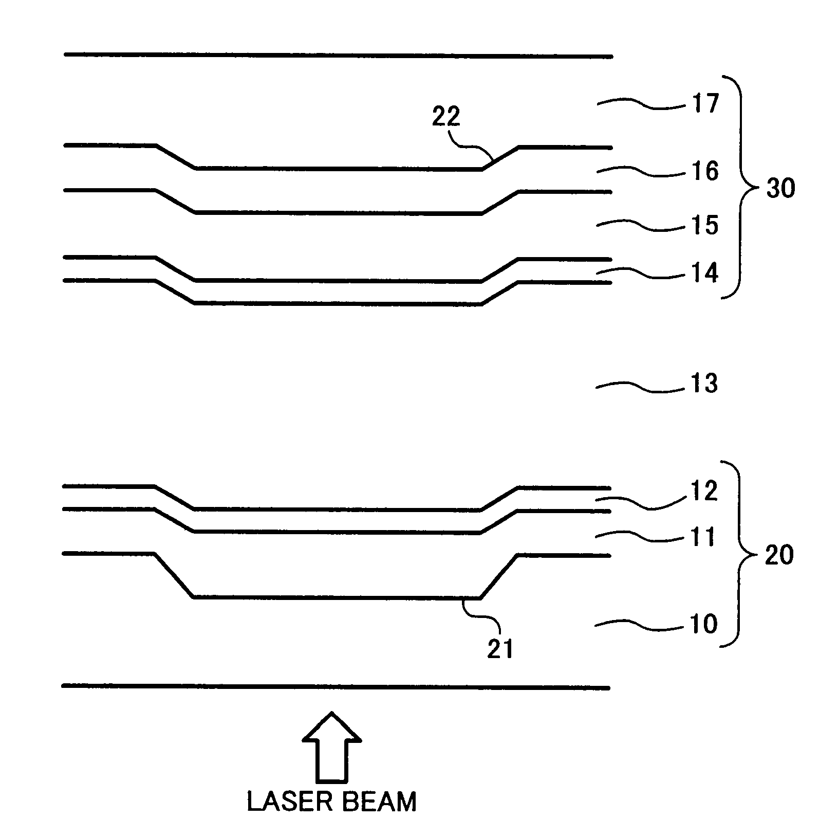
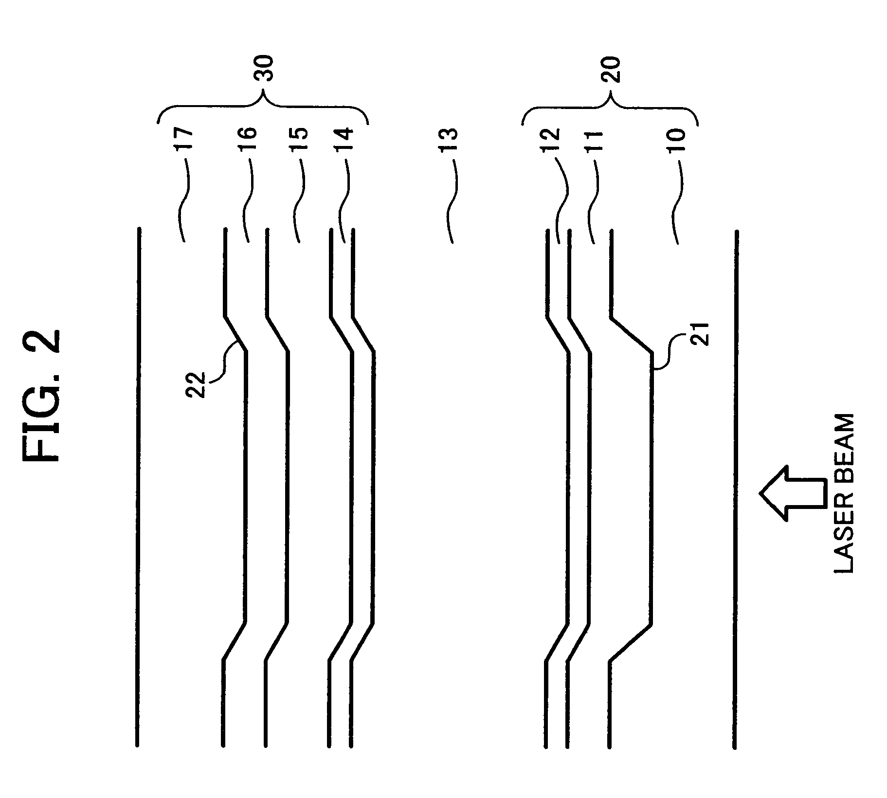
The present invention provides an optical information recording medium with double information recording layers that can record and play back information with good signal characteristics even for the layer located furthest from the side of incident light. The medium includes a first information substrate and a second information substrate with a guide groove and a recording layer containing a dye, a reflective layer, and a light transmittance protective layer. The two substrates are attached together with a transparent intermediate layer. The light transmittance protective layer has a refractive index and absorption index that satisfies certain relationships. The refractive index and thickness of the light transmittance protective layer are preferred to be within certain ranges. The light transmittance protective layer contains ZnS and a transparent electroconductive oxide. The ratio of ZnS in the light transmittance protective layer is also preferred. The light transmittance protective layer may have multiple layers with different refractive indices. These technical effects improve the performance of the optical information recording medium.

Problems solved by technology

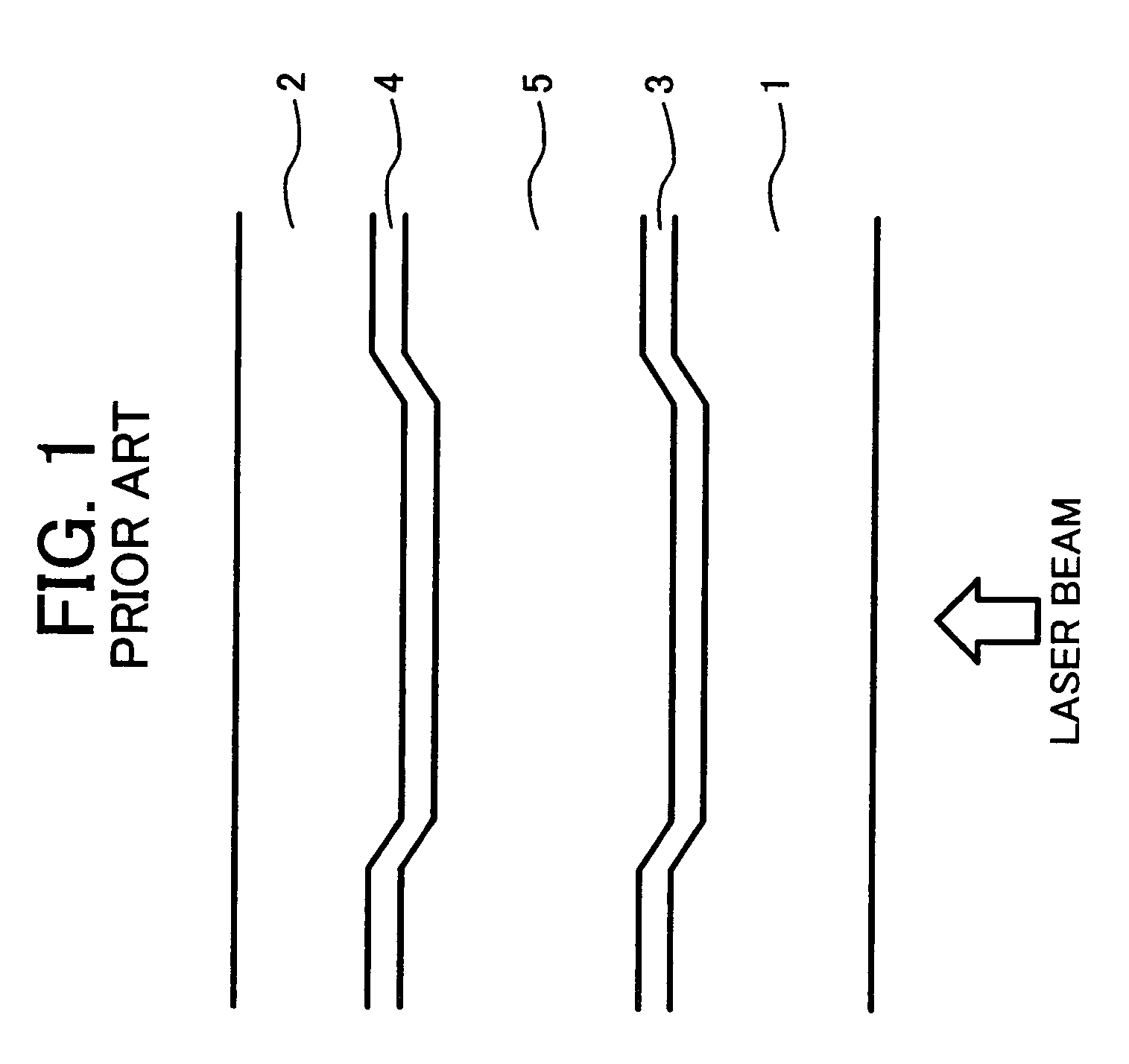
When an optical pickup irradiates with a writing laser beam the information recording layer located at the back in an optical information recording medium in which information is recorded and read in double information recording layers from one side with its focus thereon there is a problem in that the other information recording layer located at the front therein attenuates the power of the laser beam so that the medium does not have a good combination of optical absorption necessary to record information in the second information recording layer and optical reflection therefrom.
Therefore, the medium does not solve the problem of optical absorption and reflection deriving from the second information recording layer mentioned above.
However, there is no specific description about manufacturing conditions and optical characteristics.

Method used


Image

  • Optical information recording medium
  • Optical information recording medium
  • Optical information recording medium

Examples


examples 1 to 4

[0053]A coating liquid in which a squarilium dye compound represented by the following Chemical formula 1 was dissolved in 2,2,3,3-tetrafluoropropanol was coated on a polycarbonate substrate (first substrate) having the following dimension to form a first recording layer.

[0054]Dimension of the polycarbonate substrate:

[0055]

diameter 120 mmthickness0.58 mm

[0056]Guide groove having convexoconcave patterns on the polycarbonate substrate

[0057]

depth 140 nmwidth0.25 μmtrack pitch0.74 μm

[0058]The maximum absorption wavelength of this recording layer was 609 nm and the absorption level was 0.6 at the maximum absorption wavelength. On the first recording layer, a first reflective layer having a thickness of 9 nm formed of Ag99.5In0.5 was formed under the following conditions:

[0059]Sputtering device: BIGSPRINTER (manufactured by Unaxis Co. Ltd.)

[0060]Sputtering gas: Ar

[0061]Sputtering pressure: 6.0×10⁻³ torr

[0062]Sputtering power: 3.5 kW

[0063]A second reflective layer having a thickness of app...

examples 5 to 19

[0071]Optical information recording media for Examples 5 to 19 were obtained in the same manner as described in Example 1 except that materials and the thickness of the light transmittance protective layer were changed as shown in Table 1.

[0072]The optical information recording media of Examples 1 to 19 were evaluated using a DVD evaluation device DDU1000 manufactured by Pulstec Industrial Co., Ltd.) with a wavelength of 657 nm and numerical aperture NA of 0.65 in the following way: Record DVD (8 to 16) signals with an optimal recording power Po (mW) (i.e., the recording power at which data to data dock jitter was minimum) at a linear velocity of 9.2 m / s; and evaluate playback performance at a linear velocity of 3.8 m / s. The results are shown in FIGS. 3 to 6. The recording pulse strategy was a multiple pulse system of (n-2)T with a multiple pulse width of 10 / 16.

[0073]As seen in FIG. 3, when a refractive index was large, the reflectivity after recording I14H (%) varies in a cyclic ma...

examples 20 to 26

[0074]Optical information recording media for Examples 20 to 26 were obtained in the same manner as described in Example 1 except that materials and the thickness of the light transmittance protective layer were changed as shown in Table 1. The recording characteristics were measured in the same manner as in Example 1. The results are shown in Table 1.

[0075]As seen in Table 1, reflectivity I14 (%) at the optimal recording power, modulation depth I14 / I14H (%) and jitter (%) were excellent in Examples 20 to 26.

[0076]

TABLE 1ModulationSputterdepthLight trasnmittance protectivepowerRefractiveAbsorptionLayerReflectivity(I14 / I14H)JitterPolayer (composition ratio in mol %)sourceindexindexthicknessnd / λI14H(%)(%)(%)(Mw)Ex. 1GeS2RF2.130.0011100.35150.819.015Ex. 2GeS2RF2.130.0011300.41170.898.216Ex. 3GeS2RF2.130.0011400.45170.908.717Ex. 4GeS2RF2.130.0011500.48180.918.217Ex. 5ZnS(80)SiC(20)RF2.380.011000.36130.869.213Ex. 6ZnS(80)SiC(20)RF2.380.011200.44160.938.315Ex. 7ZnS(80)SiC(20)RF2.380.01140...


PUM

PropertyMeasurementUnit
thicknessaaaaaaaaaa
refractive indexaaaaaaaaaa

Abstract

An optical information recording medium containing a first information substrate including a first substrate having a guide groove thereon, a first recording layer including a dye, overlying the first substrate and a first reflective layer being a semi-transmittance layer, overlying the first recording layer, a second information substrate comprising, a second substrate having a guide groove thereon, a second recording layer comprising a dye, overlying the second substrate, a second reflective layer being a semi-transmittance layer, located overlying the second recording layer and a light transmittance protective layer overlying the second reflective layer and a transparent intermediate layer. Further, the following relationships (1) and (2) are satisfied: (1) 0.3≦nd / λ≦0.7, wherein n represents refractive index in the complex refractive index n-ik of the light transmittance protective layer, d represents a thickness thereof, and λ is at least one of a recording wavelength and a playback wavelength, (2) k≦0.05, wherein k represents absorption index of the light transmittance protective layer of the complex refractive index n-ik.

Description

BACKGROUND OF THE INVENTION[0001]1. Field of the Invention[0002]This document claims priority and contains subject matter related to Japanese Patent Applications Nos. 2004-081173 and 2004-343159, filed on Mar. 19, 2004, and Nov. 26, 2004, respectively, incorporated herein by reference.[0003]The present invention relates to an information recording medium in which information is recorded and played back with irradiation of a laser beam and more particularly to a double-layer Digital Versatile Disc (DVD) having two write-once information recording layers.[0004]2. Discussion of the Background[0005]In addition to read-only optical information recording media such as DVD-ROMs, recordable Digital Versatile Discs (DVD) such as DVD+RWs, DVD+Rs, DVD-Rs, DVD-RWs and DVD-RAMs have been introduced into the market. DVD+Rs and DVD+RWs are technically positioned as an extension of conventional recordable compact discs such as CD-Rs and CD-RWs. To secure compatibility between DVD+Rs and DVD+RWs and...

Claims


Application Information

Patent Timeline
Patent Type & Authority Patents(United States)
IPC IPC(8): G11B7/24B32B3/02G11B7/24027G11B7/24035G11B7/24056G11B7/24062G11B7/244G11B7/246G11B7/249G11B7/254G11B7/257G11B7/2578
CPCG11B7/246G11B7/2578Y10T428/21G11B7/2467G11B7/2472G11B7/248G11B7/249G11B7/2531G11B7/2533G11B7/2534G11B7/2535G11B7/259G11B2007/25706G11B2007/25708G11B2007/2571G11B2007/25711G11B2007/25713G11B2007/25715G11B2007/25716G11B2007/25718G11B7/2463
Inventor NAKAMURA, YUKIYASHIRO, TOHRUMIKAMI, TATSUO
Owner RICOH KK
Learn More