
Fluid flow-fields for electrochemical devices

a technology of electrochemical devices and fluid flow fields, which is applied in the direction of electrochemical generators, cell components, cell component details, etc., can solve the problems of high pressure drop across the mea, poor removal of by-products and water, and insufficient fuel flow distribution, so as to improve flow distribution and by-product removal, the effect of optimizing the pressure drop

Inactive Publication Date: 2006-08-29
EI DU PONT DE NEMOURS & CO
View PDF11 Cites 6 Cited by
  • Summary
  • Abstract
  • Description
  • Claims
  • Application Information

AI Technical Summary

Benefits of technology

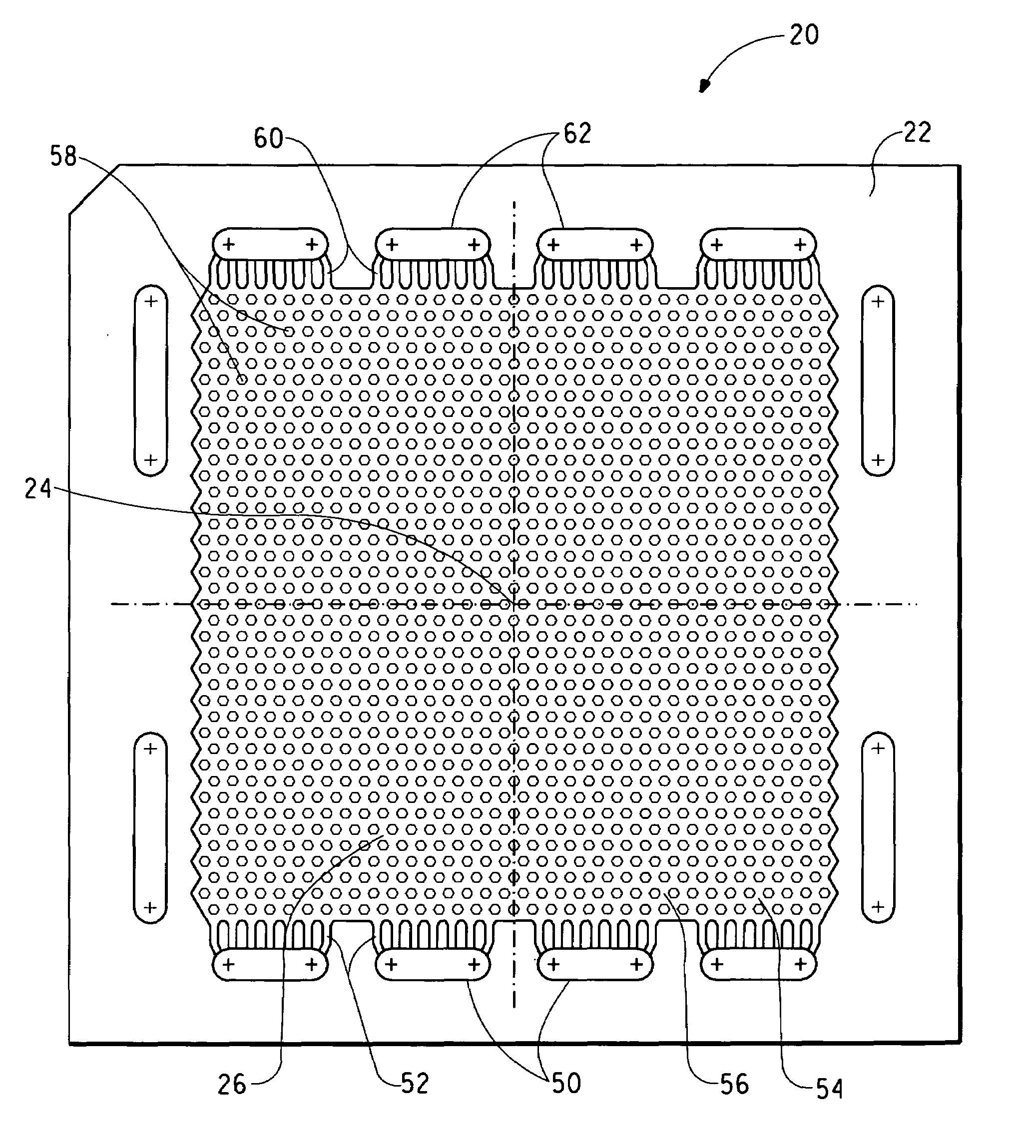
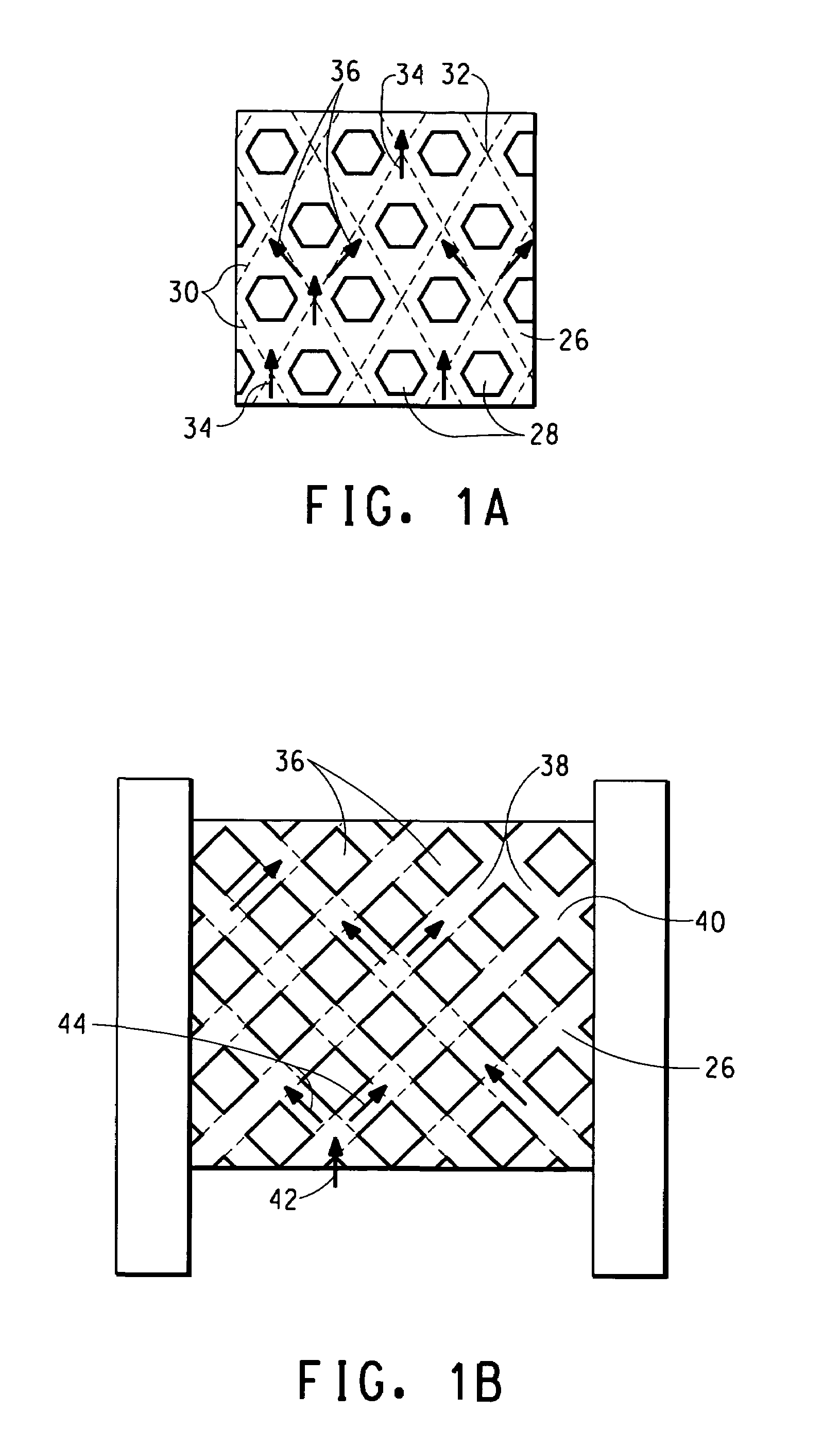
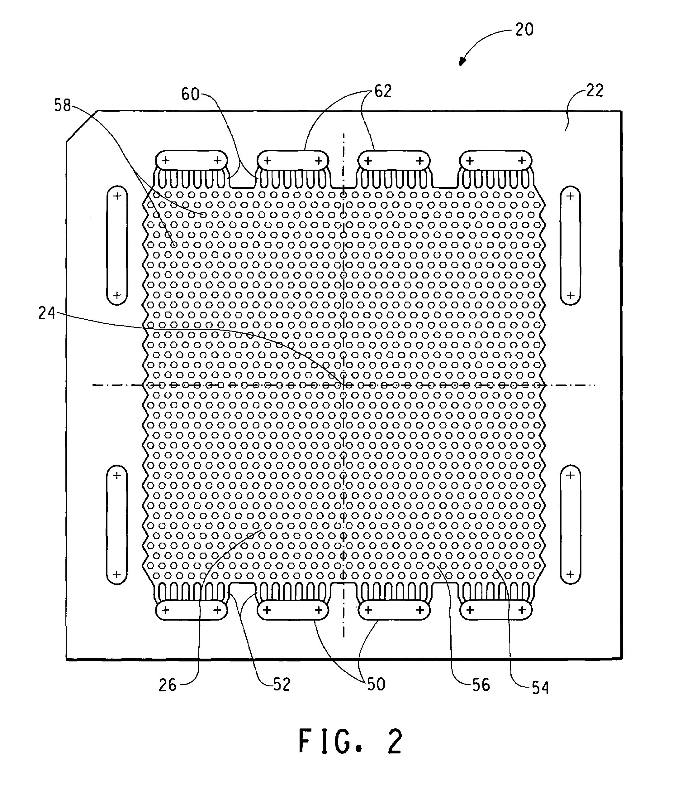
[0018]The present invention provides fluid flow field designs comprising combinations of diagonal channels and orifices. The diagonal channels provide pathways to distribute the reactant fuel in all directions a flow field and has orifices to optimize the pressure drop in the fuel flow channels between the inlet and outlet manifolds, thereby improving flow distribution and by-product removal.

Problems solved by technology

Recently, several problems have been recognized in the art with respect to flow field design and the reactant flow channel configurations, especially in fuel cells that use liquid fuels such as methanol as reactants.
Key problems with these prior art designs include inadequate fuel flow distribution, high pressure-drops across the MEA and poor removal of by-products and water.
Pin-design flow fields result in low reactant pressure drop across the corresponding flow field, however, reactants flowing through such flow fields tend to follow the path of least resistance across the flow field that may result in channeling and the formation of stagnant areas.
This in turn results in poor fuel cell performance.
However, this channeling of reactant across the active area results in a relatively high reactant flow path length that creates a substantial pressure drop and significant concentration gradients from inlet to outlet.
Additionally, the use of a single channel to collect the entire liquid water product from the electrode may promote flooding of the single serpentine, especially at high current densities.
The flow field designs described have certain drawbacks, especially in fuel cells using methanol as the reactant fuel.
The main drawbacks include:Unfavorable pressure drop across the flow field.
Long, narrow flow paths, as found in the serpentine designs, lead to high pressure drops inside the flow channels.
In these cases, high parasitic power is required to pressurize the reactants.Stagnant areas within the flow field.
The reaction rate of the fuel cell is normally slower in stagnant areas, hence significantly affecting the performance of the fuel cell.
The formation and presence of stagnant areas leads to ineffective utilization of the electrode catalyst.
In cases where the reactants are in the gas phase while the by-products are liquid, poor removal and accumulation of the by-products inside the cell will promote flooding.
Flooding reduces the efficiency of the fuel cell since less reactant is exposed to the catalyst in the electrode.High concentration gradients of reactants across the flow field.
Long flow paths may cause significant concentration gradients from the inlet to the outlet of the fuel cell, and lead to non-uniform current distribution through the fuel cell.

Method used


Image

  • Fluid flow-fields for electrochemical devices
  • Fluid flow-fields for electrochemical devices
  • Fluid flow-fields for electrochemical devices

Examples


Embodiment Construction

[0036]A typical fuel cell reactor may comprise a single-cell, or a multi-cell stack. In either case, the membrane / electrode assembly (MEA) comprising the proton-conducting membrane (the electrolyte) and the anode and cathode, is typically sandwiched between two highly (electrically) conductive flow field plates. The cathode and the anode typically comprise a porous backing made of an electrically conductive material, such as carbon paper, cloth or felt, and an electrocatalyst layer bonded to the porous backing. The electrocatalyst layers of each electrode comprise a mix of electrocatalyst particles and proton-conducting particles.

[0037]The flow field plate is made of an electrically conductive material, and is preferably made from non-porous nuclear grade carbon blocks. However, other conventional electrically conductive materials such as electrically-conductive polymers, corrosion resistant metals, and graphite / polymer composites are used to make the flow field plates. As seen in F...


PUM

PropertyMeasurementUnit
electrically conductingaaaaaaaaaa
shapeaaaaaaaaaa
sizeaaaaaaaaaa

Abstract

Disclosed is a novel fluid flow field plate for use in a solid polymer electrolyte fuel cell. The flow field plate is made of a suitable electrically conducting material and comprises a substantially planar surface, a flow field formed in said substantially planar surface, said flow field comprising a plurality of staggered lands defining a network of substantially symmetric interconnected orifices and diagonal channels in the flow field and a fluid supply manifold through which fuel and an oxidant are introduced to the flow field and a fluid exhaust manifold through which reaction by-products and excess fuel and oxidant are removed from the flow field. Streams of the fuel, oxidant and reaction by-products are continually separated and diverted into separate channels, and the separated streams are then mixed with streams from adjacent channels in the orfices.

Description

FIELD OF THE INVENTION[0001]This invention relates to new electrochemical fuel cells, and in particular to the design of fluid flow fields for the electrically conductive plates.TECHNICAL BACKGROUND OF THE INVENTION[0002]A fuel cell is a galvanic cell that generates electrical energy by converting chemical energy, derived from a fuel supplied to the cell, directly into electrical energy by an electrochemical process in which the fuel is oxidized in the cell. A typical fuel cell includes an anode, a cathode, electrocatalysts and an electrolyte housed in a casing. The fuel material and oxidant are continuously and independently supplied to the anodes and cathodes, respectively, where the fuel and oxidant react chemically to generate a useable electric current. The reaction by-products are withdrawn from the cell.[0003]A great advantage of a fuel cell is that it converts chemical energy directly to electrical energy without the necessity of undergoing any intermediate steps, for exampl...

Claims


Application Information

Patent Timeline
Patent Type & Authority Patents(United States)
IPC IPC(8): H01M2/14H01M8/02H01M8/10
CPCH01M8/0258H01M8/026Y02E60/50H01M2008/1095H01M8/2483H01M8/241
Inventor ABDOU, MOHAMEDANDRIN, PETERBISARIA, MUKESH K.
Owner EI DU PONT DE NEMOURS & CO
Learn More