In-line holographic mask for micromachining

a micro-machining and holographic mask technology, applied in the field of microlithography, photopatterning, machining and materials processing, can solve the problems of inefficient use of available light, thermal damage to the workpiece, and localized disassociation of the material with little or no heating of the workpiece, etc., and achieve the effect of high-efficiency in-lin

Inactive Publication Date: 2006-08-29
MARSUPIAL HLDG
View PDF28 Cites 35 Cited by
  • Summary
  • Abstract
  • Description
  • Claims
  • Application Information

AI Technical Summary

Benefits of technology

[0029]The present invention is an optically made, high-efficiency in-line holographic mask (ILHM) for in-line holographic patterning of a workpiece, and apparatus and methods for performing same. The ILHM of the present invention combines the imaging function of a lens with the transmission properties of a standard amplitude mask, obviating the need for expensive projection optics. In forming the ILHM, two types of object masks are used: type I object mask

Problems solved by technology

However, such localized heating can have the undesirable side-effect of thermally damaging the workpiece.
Sufficient excitation of the bonding electrons with a tightly focused beam results in the localized disassociation of the material with little or no heating of the workpiece.
While this method is capable of forming small well-defined spots and is well-suited for forming arbitrary shapes or figures, the method is inefficient with its use of available light because the mask blocks a portion of the beam in order to form the pattern.
Also, the step-and-repeat method is time-consuming, particularly when hundreds or thousands of spots need to be patterned on each of a multitude of workpieces.
However, this apparatus is fairly complex and expensive, and is generally not well-suited for forming arbitrary shapes and figures, and it has limited processing capacity or “thruput” (up to about 1000 holes/second) because of its serial mechanical nature.
However, these multiple-focusing apparatus and methods also have their own shortcomings and limitations.
While this system operates in-line, it is fairly complex because the projection lens for most applications would not be a single lens element, but a multi-element well-corrected lens system capable of imaging very small features.
While this technique allows for a multitude of holes to be patterned simultaneously with a single exposure, it is not well-suited for patterning generalized “non-hole” type objects, i.e., objects having significant physical extent.
This is disadvantageous because each of the multitude of discrete FZP elements needs to be aligned to a specific location on the workpie

Method used


Image

  • In-line holographic mask for micromachining
  • In-line holographic mask for micromachining
  • In-line holographic mask for micromachining

Examples


Embodiment Construction

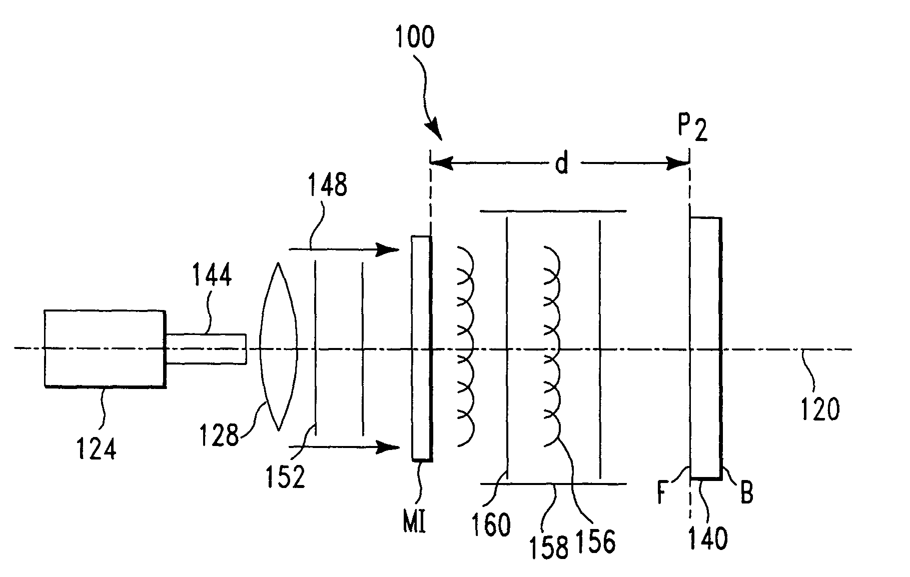
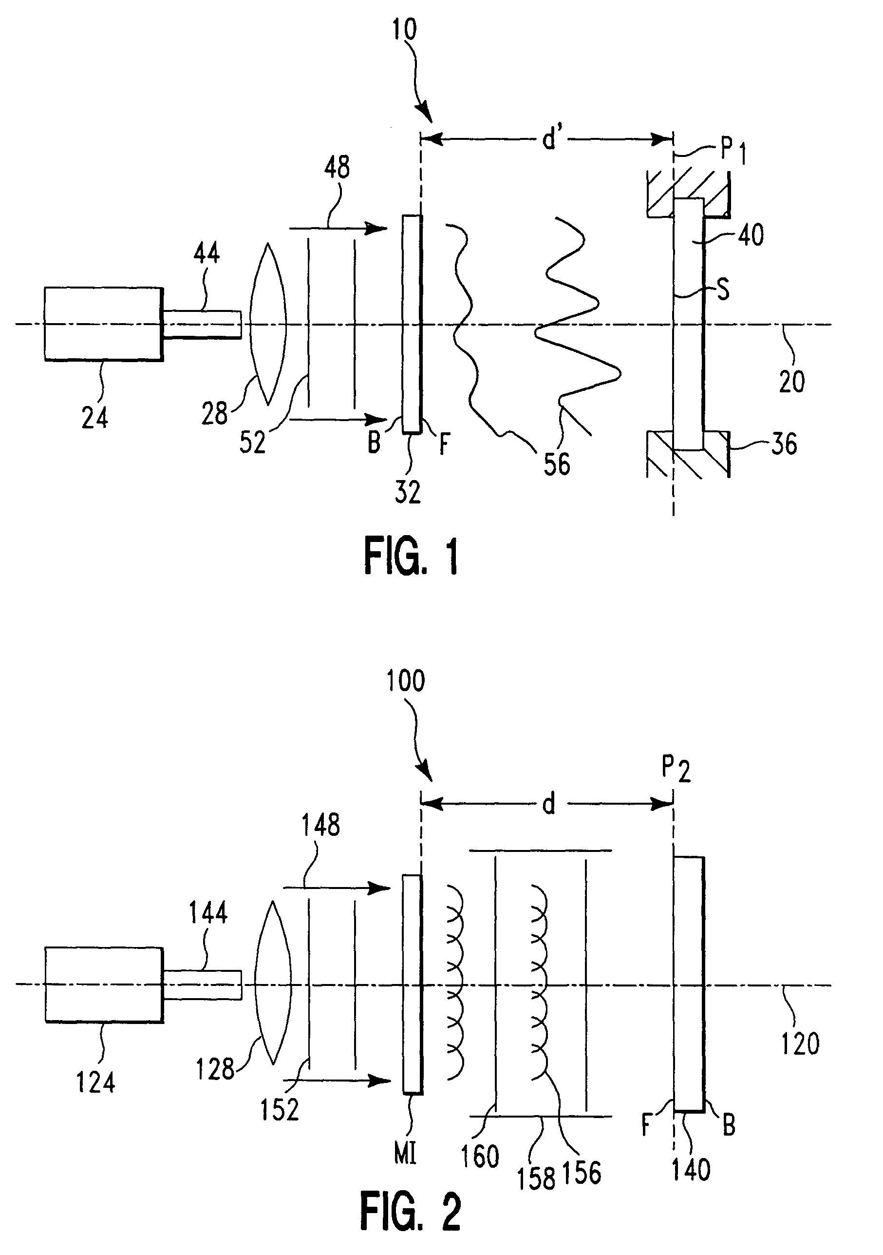
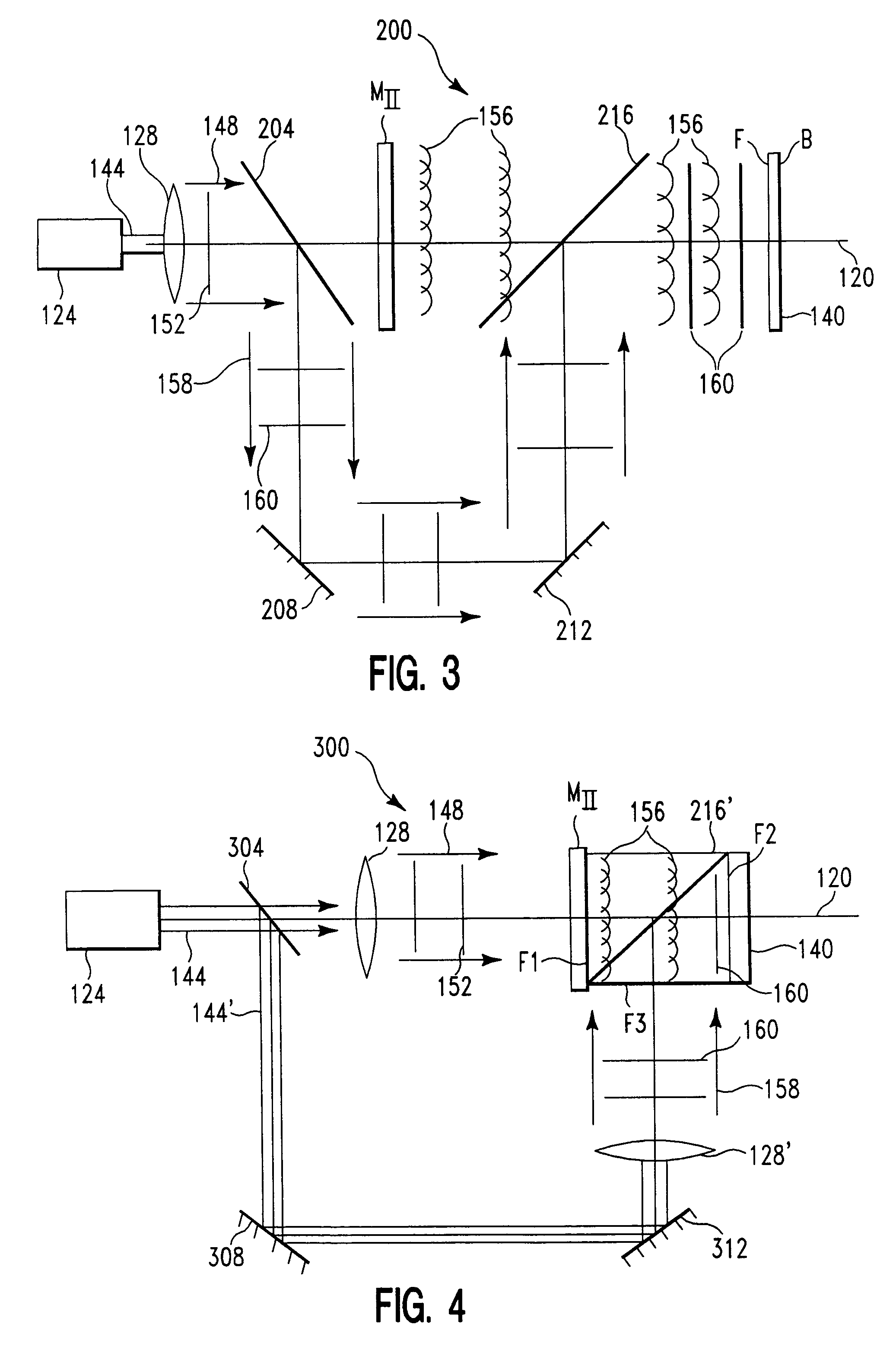
[0059]The present invention is an optically made, high-efficiency in-line holographic mask (ILHM) for in-line holographic patterning of a workpiece and apparatus and methods for performing same. The ILHM of the present invention combines the imaging function of a lens with the transmission properties of a standard amplitude mask, obviating the need for expensive projection optics. Because the ILHM of the present invention is optically made (as opposed to computer generated), a wide variety of features of varying complexity can readily be patterned on a workpiece. Further, the ILHM is not limited to discrete phase or transmission values as an approximation to the holographic interference pattern, but contains a wide range of phase information present in the diffracted wavefronts from a real object. Further, it will be understood that the present invention has application for wavelengths ranging from the IR to the x-ray region of the electromagnetic radiation spectrum.

[0060]For applic...


PUM

PropertyMeasurementUnit
Ratioaaaaaaaaaa
Transparencyaaaaaaaaaa
Optical densityaaaaaaaaaa

Abstract

A method of fabricating a holographic mask includes the steps of providing an illumination source and a non-opaque object mask. The source is for generating a coherent illumination beam directed along an axis. The object mask is capable of transmitting a portion of the illumination beam as undiffracted reference wavefronts. The object mask has one or more substantially transparent elements for creating overlapping object wavefronts when the illumination beam is incident thereon. The object mask is disposed in the illumination beam. A holographic recording medium is provided in the illumination beam in line optically with the object mask. The object mask is illuminated with the illumination beam, thereby causing the object mask to allow undiffracted reference wavefronts to pass therethrough. The illumination directed along the axis causes the one or more substantially transparent elements to create object wavefronts which interact with the undiffracted reference wavefronts to create an interference pattern.

Description

[0001]This application is a divisional of U.S. patent application Ser. No. 08 / 972,464, filed Nov. 14, 1997, now U.S. Pat. No. 6,618,174, which claims the benefit of U.S. Provisional Application No. 60 / 030,962, filed on Nov. 15, 1996.FIELD OF THE INVENTION[0002]The present invention relates to methods and apparatus for microlithography, photopatterning, machining and materials processing and, more particularly, to high-efficiency in-line holograms that combine the functions of a lens and a standard amplitude mask in one device.BACKGROUND OF THE INVENTION[0003]There are many industrial applications and processes that require precise patterning of a workpiece, two such applications being, for example, fabricating microcircuits, and forming circuit board interconnections. For instance, the demand for compact electronics packaging has seen the means for forming interconnections among microcircuits evolve from the use of peripheral interconnections (i.e., connections around the edge of th...

Claims


Application Information

Patent Timeline
IPC IPC(8): G02B5/32B23K26/06G03F7/20G03H1/04
CPCB23K26/0656G02B5/32G03F7/70408G03H1/0404Y10S359/90G03H2001/2289G03H2210/12G03H2210/20G03H2240/52G03H2001/0094B23K26/066
Inventor PARKER, WILLIAM P.PARKER, JULIE W.
Owner MARSUPIAL HLDG
Why Eureka
Try Eureka