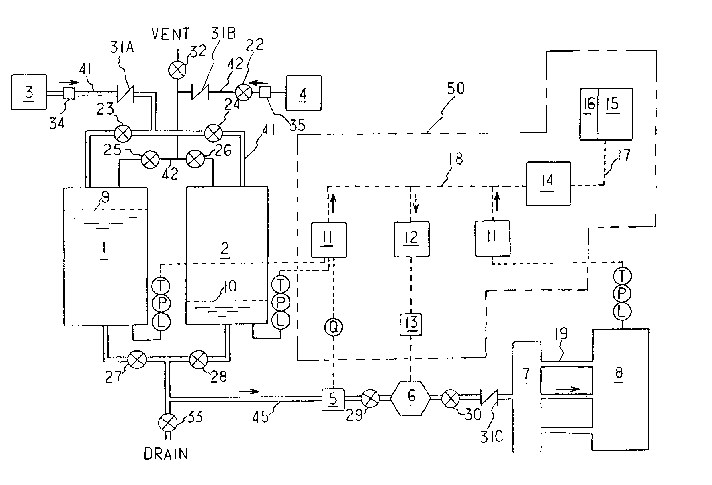
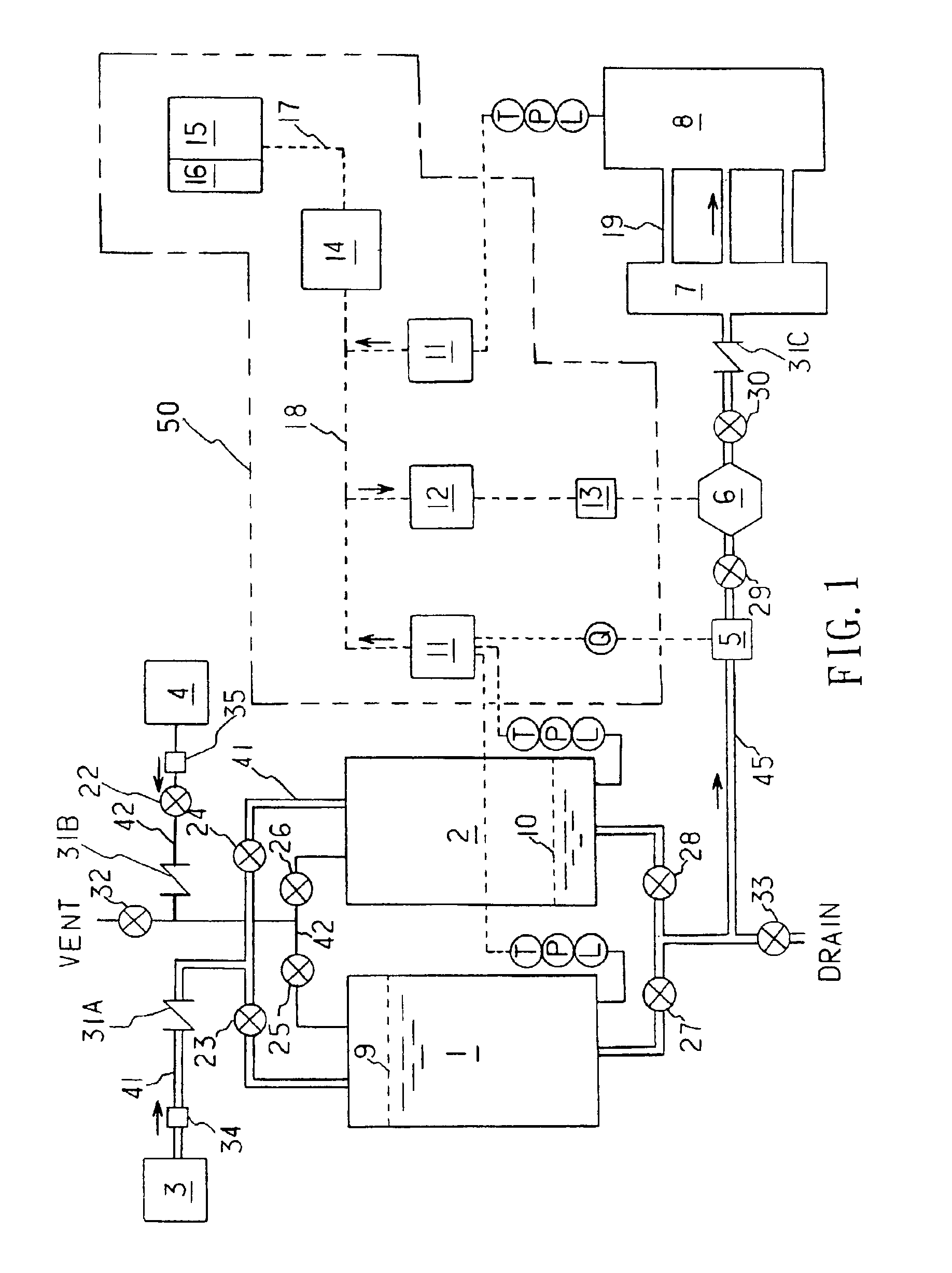
[0013]The fluid feed function is activated with the opening of the feed fluid
isolation valve at the bottom of one of the feed fluid tanks, and the
tank pressure can be maintained, or replenished at time of feeding operation, depending on actual needs, by automatic or manual
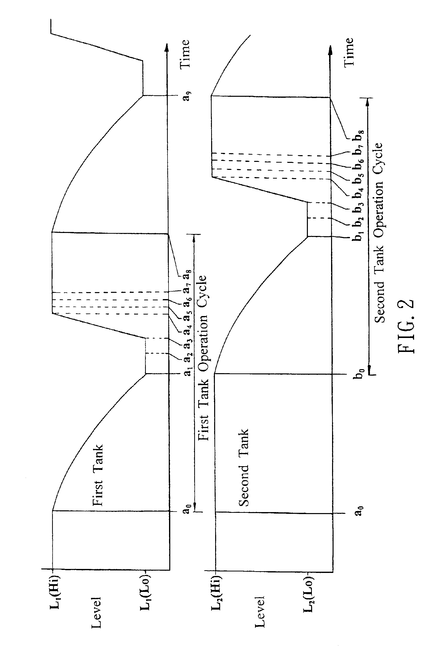
pressure regulator. When the lowest-level warning
signal is indicated, with the speedy switching of the valve sets, the fluid feeding operation is switched over, from the one tank having been running fluid feed operation, to the other one having been at initial standby state, thus continuing with the operation. By doing so, not only can the gas inside the tanks be prevented from entering the external system by incident, but also can the tanks be rebuilt to the initial standby state while the other tank is in charge of the fluid feeding. With such cyclic switching
operation mode, the system of the present invention can meet long-term requirements of the external systems, enabling the function of continuous fluid feeding to be achieved.(2) The Measuring and Regulating Component
[0014]The measuring and regulating component includes a
measuring instrument and valves installed on the transmission
pipe lines between the feed fluid outlet and the inlet of the external systems, being the main part performing the measuring and flow controlling of the feed fluid. Accurate controlling of the flow of feed fluid can be achieved through various types of valves. For example, by means of
electric current / pressure (I / P) converter, pneumatic flow control valve can control the
valve opening, while the actual flow rate as measured by the associated flow meter can serve as
cross reference in comparison. The
control unit can automatically regulate the opening of the
control valves to quickly rectify the flow rate of the feed fluid, so that the accuracy of the fluid feeding control meet requirements by the external systems.
[0016]The function of the
throttle valves installed at each end of the flow control valve, apart from adjusting the application range of the feed fluid flow rate, is to lower the excessive valve coefficient (Cv) variations resulting from the pressure differentials between the up and down streams of the control valve, thus increasing the stability of the flow rate after the regulation by the control valve. In addition, the check valves installed on each transmission pipe line ensure that under no circumstance will the feed fluid in the tank flow back to the sources of the
fluid supply and
gas supply, and prevent fluid in the external system from flowing back to the feed fluid tanks.(3) The
Control Unit[0021]The control unit comprises: a
data acquisition and controller, an input
signal module, an output
signal module, and a signal
transmitter, the input signal module acquiring the original signals of each
measuring instrument, (e.g. pressure, temperature, and
fluid level), the output signal module transmitting 4-20 mA control signals to rectify the opening of the flow control valve. The signal
transmitter transmits and receives signals, featuring reducing interfering
noise and fast transmission. The
data acquisition and controller instantaneously gathers the original signals of each
measuring instrument, converts the signals into physical quantities, and is then compared and judged against the built-in data preset in the control unit. After that, the function of automatic operation of continuous fluid feeding is accomplished through the decisions on whether or not the open / close state of each of the
isolation valve controlling the gas or
fluid supply, gas venting, fluid feeding, and the two tanks switching. When the above-mentioned measuring signals meet the preset action signals built in the control unit, (e.g. high / low
fluid level, and high / low pressure), the control unit will send out action commands for execution through human-
machine interface. The function of feed fluid flow
rate control is accomplished through a human-
machine interface driven flow control valve to instantaneously rectify the feed fluid flow rate. With the above-mentioned control unit performing the integrated functions of
data acquisition, storing, comparisons and judgments, and giving control commands, the present invention achieves the functionality of continuous fluid feeding by
automation operation and feed
fluid control.

