Capillary assay device and method

a capillary assay and assay technology, applied in the direction of fluorescence/phosphorescence, luminescent dosimeters, optical radiation measurement, etc., can solve the problems of reducing the volume of assays to microliters, changing the concentration of reagents in solution, etc., to reduce evaporative loss and improve optical signal detection

Inactive Publication Date: 2006-09-19
CORNING INC
View PDF18 Cites 4 Cited by
  • Summary
  • Abstract
  • Description
  • Claims
  • Application Information

AI Technical Summary

Benefits of technology

[0007]To reduce evaporative loss as well as improve optical signal detection from an analytical sample, the present invention provides a multi-capillary device for high-throughput screening of low-volume assays. According to the invention, the capillary device comprises: a number of collection structures; a capillary channel, adapted to contain a sample volume, running length-wise along an axis substantially parallel with a major axis of each collection structure; and each collection structure having a shape effective to either concentrate or direct an optical signal from said capillary channel towards a detector. Preferably, the axis of the capillary channel is co-axial with the collection structure. Each collection structure is embodied with a largely solid geometry having a major and a minor axial end, which is adapted to direct an optical signal emitted from an analyte in the sample volume towards the detector by means of reflection, hence incorporating a mirrored surface. The geometry of the collection structure, preferably, incorporates a surface, generated by rotating about an axis, part of at least one of the following: a cone, an ellipse, or a parabola. The radius of rotation can be either of a fixed or variable length. The capillary walls and collection structure are made from a transparent material having an index of refraction that is at least the same, preferably greater than that of the sample volume in the capillary channel.

Problems solved by technology

Several difficulties arise, however, as assay volumes are reduced to microliter and sub-microliter amounts.
First, very low volumes of aqueous solutions tend to evaporate rapidly, which causes the concentrations of reagents in solution to change as the amount of water changes.
As a consequence, small volume assays often fail to give consistent, accurate results.
Second, signals generated from small-volume assays can be imperceptibly low, which may often generate false negative or positive results.
Since long exposure times are required for detection of low signal levels by charge-coupled devices (CCD), the ability to process assays quickly with high-throughput capacity is compromised.
Unfortunately, these techniques appear to be of moderate success for addressing the issue of evaporation, and of even more limited effectiveness for improving signal detection.
A microplate format is not properly configured for efficient collection or direction of an optical signal.
Fluorescence based assays typically utilize wells with black, light absorbing walls that keep the background from the plate low but have the disadvantage of absorbing the majority of the assay signal.
As signal intensity becomes of greater and greater importance as assay volume decreases, these issues become more and more inhibitory to plate performance.
This design, however, can not be adapted easily for use with a conventional microplate, and is not compatible with current robotically automated assay processing equipment.
The spatial orientation and configuration of the capillaries makes integration with a microplate difficult.

Method used


Image

  • Capillary assay device and method
  • Capillary assay device and method
  • Capillary assay device and method

Examples


first embodiment

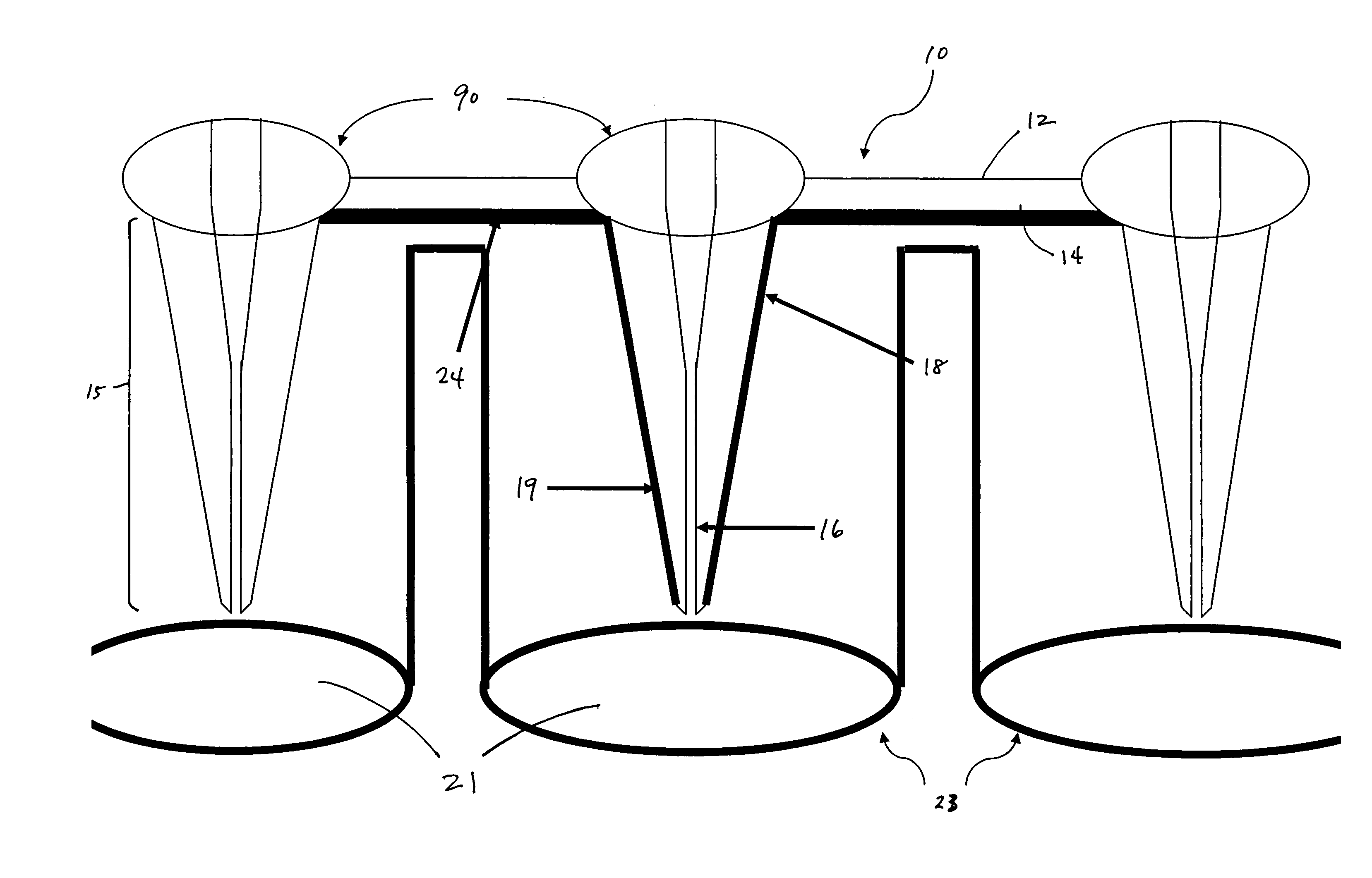
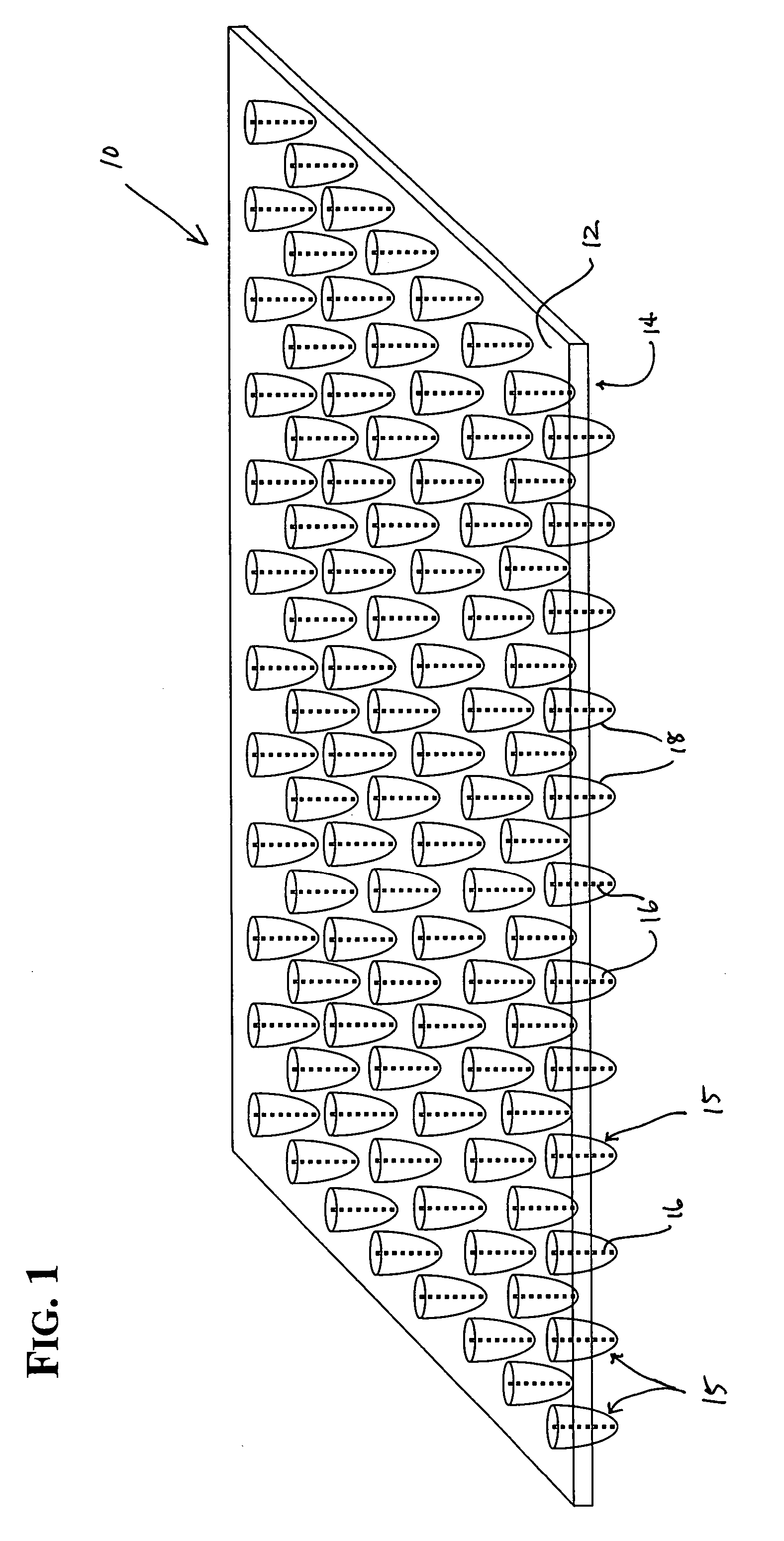
[0059] individual collectors are situated preferably in a rectilinear grid, spaced on-center to correspond with the wells of a microplate of industry-standard dimensions (e.g., 96, 384, 1536 well matrix) and other irregular configurations. When used as a lid for a microtiter plate, assay reaction components can be dispensed into microplate wells as usual. Each collection structure is inserted into a corresponding well 21 of the plate 23 containing a fluid or aqueous assay solution, such as in FIG. 12. The embodiment illustrated in FIG. 1, for example, is tailored to nest within a 96-well plate. The solutions are drawn up the capillaries if the tip of the projection is in contact with the solution. When using a solution of very low fluid volume, one may wish to compress the device against the microplate 23 to ensure each collector and capillary 16 contacts the solutions and fills the capillary. In such situations, an elastomeric layer 24 that is situated against the second or lower s...

second embodiment

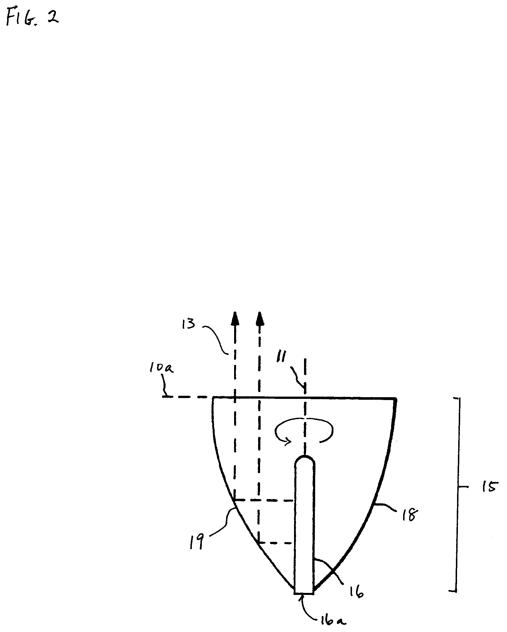
[0060]Alternatively, the device can be used independently of the microtiter well plate. If an upper opening for a capillary extends through to the first or upper surface of the platen, fluids or reagents can be dispensed directly into the capillary from the top of the platen, enabling the device to be used in likewise fashion but without a microplate. In a hybrid technique, one may first prepare a well plate with solution or samples, insert the collector and capillary end into the sample, then remove and read the signal separate from the well plate.

[0061]In either embodiment, fluid in the capillary can be emptied or forced out using vacuum, centrifugation, or air pressure. The capillaries can then be readily refilled in a short time, and the desired assay procedure may be repeated. Conventionally, entrapment of air bubbles is also problematic in small diameter wells. This issue is not a problem in the present device since a capillary can be open at both ends. When solution fills th...


PUM

PropertyMeasurementUnit
conical angleaaaaaaaaaa
thicknessaaaaaaaaaa
thicknessaaaaaaaaaa

Abstract

A device and method for detecting a signal from an analytical sample is provided. The device comprises a platen with a first and second surface, a number of collection structures extending from the second surface. Each collection structure has a capillary channel running along a common axis as the collection structure from the platen to a terminal end of the structure. Within the capillary channel are sample analytes of interest. On the first surface is disposed a number of optical elements, corresponding to each collection structure, each centered on a capillary channel. Each collection structure has a geometry that can concentrate an optical emission from within the capillary channel, along the entire length of the capillary channel, towards the first surface and optical elements, to a detection device, by means of either mirrored surface reflection or total internal reflection. The collection structure may also direct a light beam into the capillary channel. The present device can be used for non-imaging optical applications from the generated signal.

Description

CLAIM OF PRIORITY[0001]The present Application claims benefit of priority from U.S. Provisional Application No. 60 / 435,641, filed Dec. 20, 2002, the content of which is incorporated herein.FIELD OF THE INVENTION[0002]The present invention pertains to a device and method for high-throughput processing and analyzing of biological or chemical assays. In particular, the invention relates to a device and method that improves the transmission and detection of optical signal from a number of low-volume assays, which involve various biological or chemical molecules, tissues or cells currently or formerly in liquid suspension.BACKGROUND[0003]Biology or chemistry performed on the micro-scale, involving the reaction and subsequent analysis of quantities of reagents or analytes on the order of microliter or sub-microliter amounts, is an increasingly important aspect in the development of new therapeutic agents in the pharmaceutical and other industries. Both to conserve limited samples, reagent...

Claims


Application Information

Patent Timeline
Patent Type & Authority Patents(United States)
IPC IPC(8): G01N1/10G01J3/30G01N21/03G01N21/05G01N21/25G01N21/55G01N21/64
CPCG01N21/03G01N21/05G01N21/253G01N21/6452G01N21/552G01N2021/6467G01N2021/0346G01N2021/0357
Inventor MARTIN, GREGORY R.TANNER, ALLISON J.
Owner CORNING INC
Why Eureka
Try Eureka