
Integrated circuit devices having on-chip adaptive bandwidth buses and related methods

a technology of integrated circuits and buses, applied in the field of integrated circuit devices including buses, can solve the problems of increasing the difficulty of low propagation delays reducing distance, and difficulty in repeater insertion or in some cases inability to achieve, so as to reduce cross-talk noise, reduce propagation delays, and high signaling bandwidth

Inactive Publication Date: 2006-09-19
NORTH CAROLINA STATE UNIV
View PDF1 Cites 33 Cited by
  • Summary
  • Abstract
  • Description
  • Claims
  • Application Information

AI Technical Summary

Benefits of technology

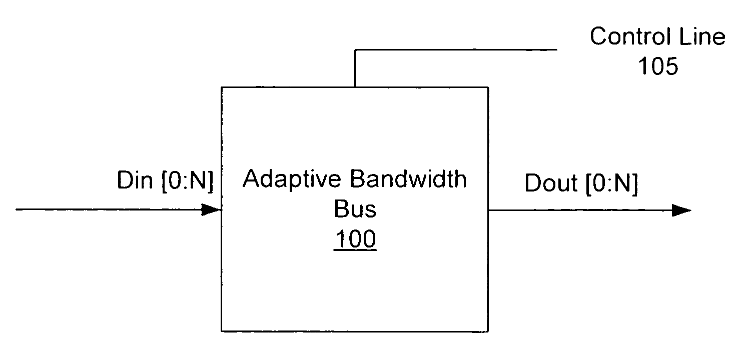
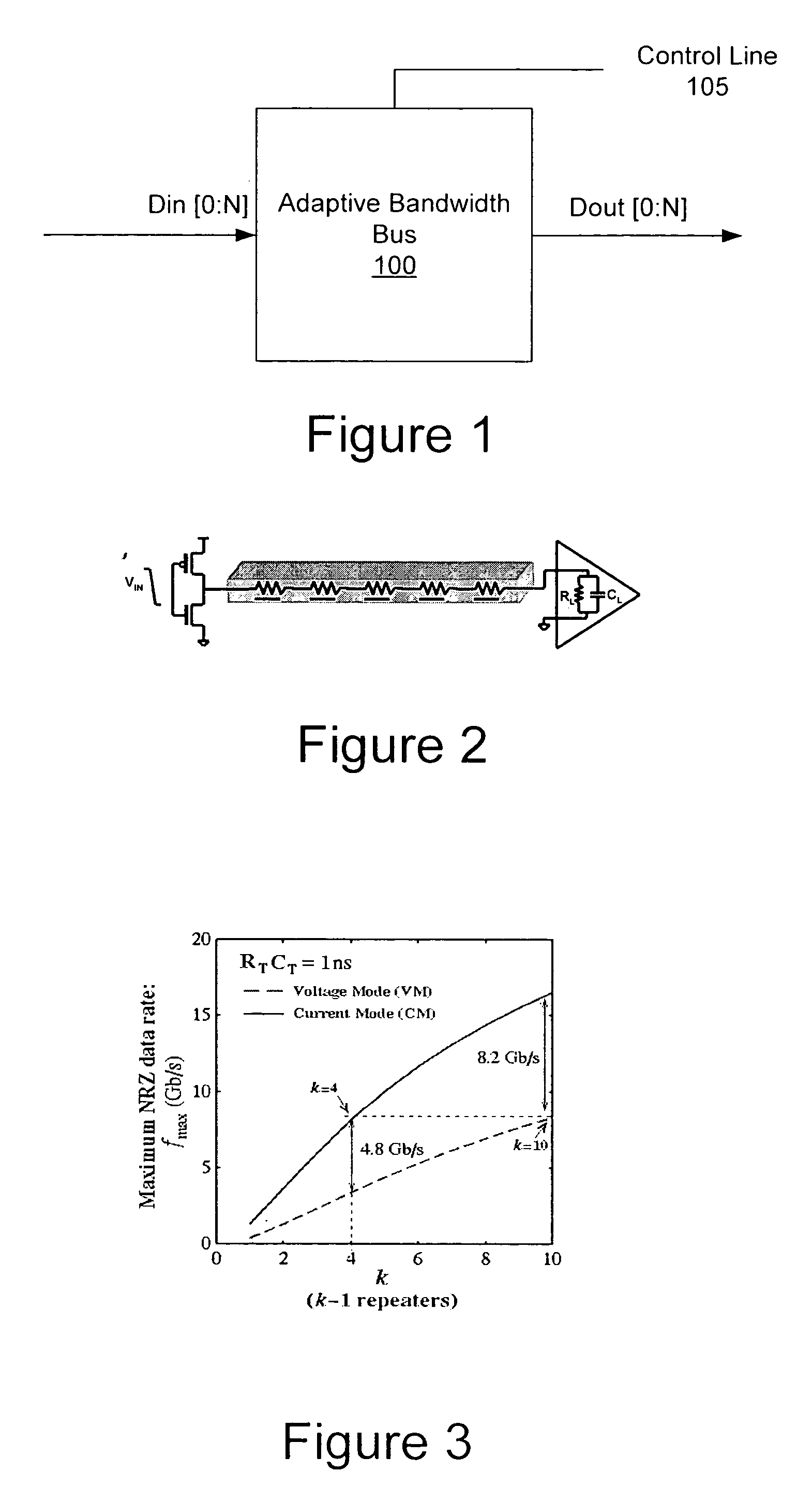
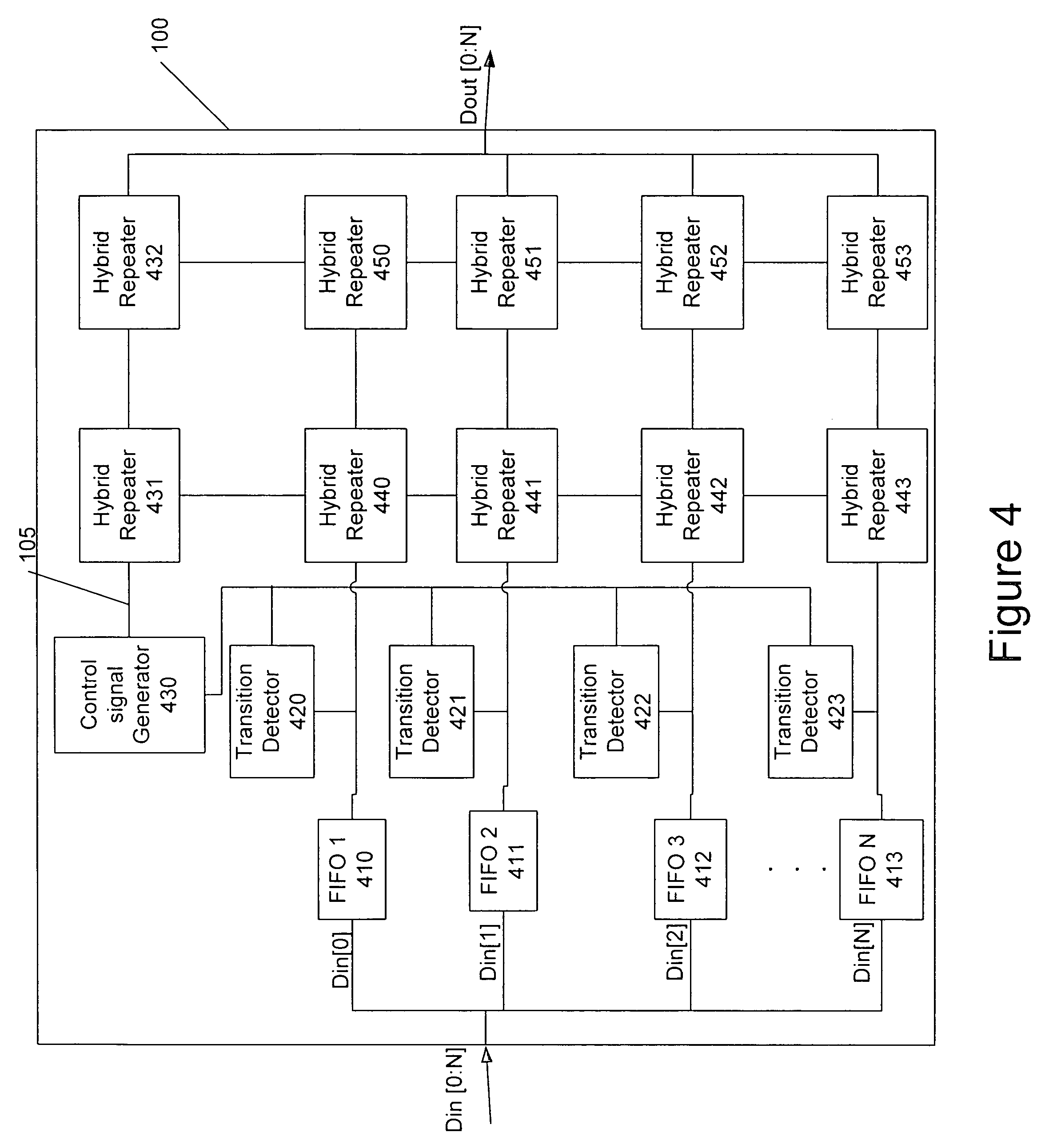
The present invention provides an adaptive bandwidth bus that can switch between a current mode and a voltage mode based on the transition of bits in an input data signal. The bus includes a transition detector and a hybrid repeater that can switch between the current mode and the voltage mode based on the detection of transitions. The overall processing delay of the bus is determined based on the transition detector and control signal delays. The bandwidth of the bus can be adjusted based on the detection of transitions. The invention also provides methods for transmitting signals over a bus in either current mode or voltage mode and adjusting the bandwidth based on the detection of transitions. The invention improves integrated circuit devices and methods with low propagation delays, high signaling bandwidth, and reduced cross-talk noise.

Problems solved by technology

However, low propagation delays and high signaling bandwidth may be increasingly difficult to achieve due to, for example, a 0.7X reverse-interconnect scaling trend, a fourteen percent increase in die (chip) size, and doubling of clock operating frequency per technology node.
Often, however, repeater insertion is difficult or in some cases cannot be achieved due to placement blockages caused by underlying critical processing units, i.e. lack of space on-chip due to the presence of components that typically cannot be removed.
Furthermore, repeater insertion distance may decrease with each technology node due to increased interconnect resistive effects, which may cause the overall improvement in delay and bandwidth to be undermined by an exponential increase in the number of repeaters on-chip and associated driver / repeater power dissipation.
The increasing clock rates may exceed, for example, 10 GHz in 2011,and the trend toward larger die sizes exemplified in many microprocessor designs, typically result in longer average interconnect lengths which may increase the electrical distances to be traversed.
However, the increase in aspect ratio with each technology generation may progressively exacerbate signal integrity problems due to increase in the ratio of the coupling capacitance between adjacent conductors to the total capacitance.
Accordingly, cross-talk noise due to inductive and capacitive coupling effects may become increasingly important and may eventually become the dominant problem over local and global propagation delays.
The potential problem due to cross-talk may be magnified due to reduced noise margins in modern high performance non-static logic circuits, for example, dynamic circuits with multiple phase clocks and pre-charge logics, which may be used to meet increased speed requirements.
Nevertheless, the implementation of low resistivity materials and low κ dielectrics may still be subject to higher production costs.
Alternatively, process scaling may impose the need for higher margins of cross-talk noise reduction, which may become progressively difficult on material and interconnect technology.
Nevertheless, the dynamic random access memory (DRAM) may pose some significant challenges due to the aggressive aspect ratios used in DRAM interconnects, leading to higher levels of noise coupling.

Method used


Image

  • Integrated circuit devices having on-chip adaptive bandwidth buses and related methods
  • Integrated circuit devices having on-chip adaptive bandwidth buses and related methods
  • Integrated circuit devices having on-chip adaptive bandwidth buses and related methods

Examples


Embodiment Construction

[0045]The present invention will now be described more fully with reference to the accompanying drawings, in which embodiments of the invention are shown. This invention may, however, be embodied in many different forms and should not be construed as being limited to the embodiments set forth herein; rather, these embodiments are provided so that this disclosure will be thorough and complete, and will fully convey the concept of the invention to those skilled in the art. In the drawings, when an element is referred to as being “coupled” or “connected” to another element, it can be directly coupled or connected to the other element or intervening elements may be present. In contrast, when an element is referred to as being “directly coupled” or “directly connected” to another element, there are no intervening elements present. Like reference numerals refer to like elements throughout.

[0046]Embodiments of the present invention will be discussed below with respect to FIGS. 1 through 24...


PUM


Abstract

An adaptive bandwidth bus is provided that switches between a current mode of operation and a voltage mode of operation. Furthermore, related methods include transmitting a data signal in a current mode or a voltage mode and transmitting a control signal to indicate whether the signal should be transmitted in the current mode or the voltage mode.

Description

FIELD OF THE INVENTION[0001]The present invention relates generally to integrated circuit devices, and more particularly, to integrated circuit devices including buses and methods related thereto.BACKGROUND OF THE INVENTION[0002]Achieving low propagation delays and high signaling bandwidth in on-chip global interconnects may be increasingly important to high-performance microprocessors and embedded systems. However, low propagation delays and high signaling bandwidth may be increasingly difficult to achieve due to, for example, a 0.7X reverse-interconnect scaling trend, a fourteen percent increase in die (chip) size, and doubling of clock operating frequency per technology node. Typically, in order to achieve low propagation delays and increased throughput data transfers within computational units on-chip, repeaters are systematically inserted in long global buses. Often, however, repeater insertion is difficult or in some cases cannot be achieved due to placement blockages caused b...

Claims


Application Information

Patent Timeline
Patent Type & Authority Patents(United States)
IPC IPC(8): H04J3/16H01L23/48G06F13/00H02MH04L12/56
CPCH04L47/10
Inventor BASHIRULLAH, RIZWANLIU, WENTAICAVIN, III, RALPH K.
Owner NORTH CAROLINA STATE UNIV
Learn More