Pulsed excitation of inductively coupled plasma sources

Active Publication Date: 2006-10-03
AES GLOBAL HLDG PTE LTD
View PDF7 Cites 47 Cited by
  • Summary
  • Abstract
  • Description
  • Claims
  • Application Information

AI Technical Summary

Benefits of technology

[0007]The reaction rate of a feed gas flowed into a plasma chamber is controlled. In one embodiment a pulsed power supply repeatedly applies a high power pulse

Problems solved by technology

However, higher power levels also increase the power dissipated to the chamber walls.
As a result, in plasma sources operated in C

Method used


Image

  • Pulsed excitation of inductively coupled plasma sources
  • Pulsed excitation of inductively coupled plasma sources
  • Pulsed excitation of inductively coupled plasma sources

Examples


Embodiment Construction

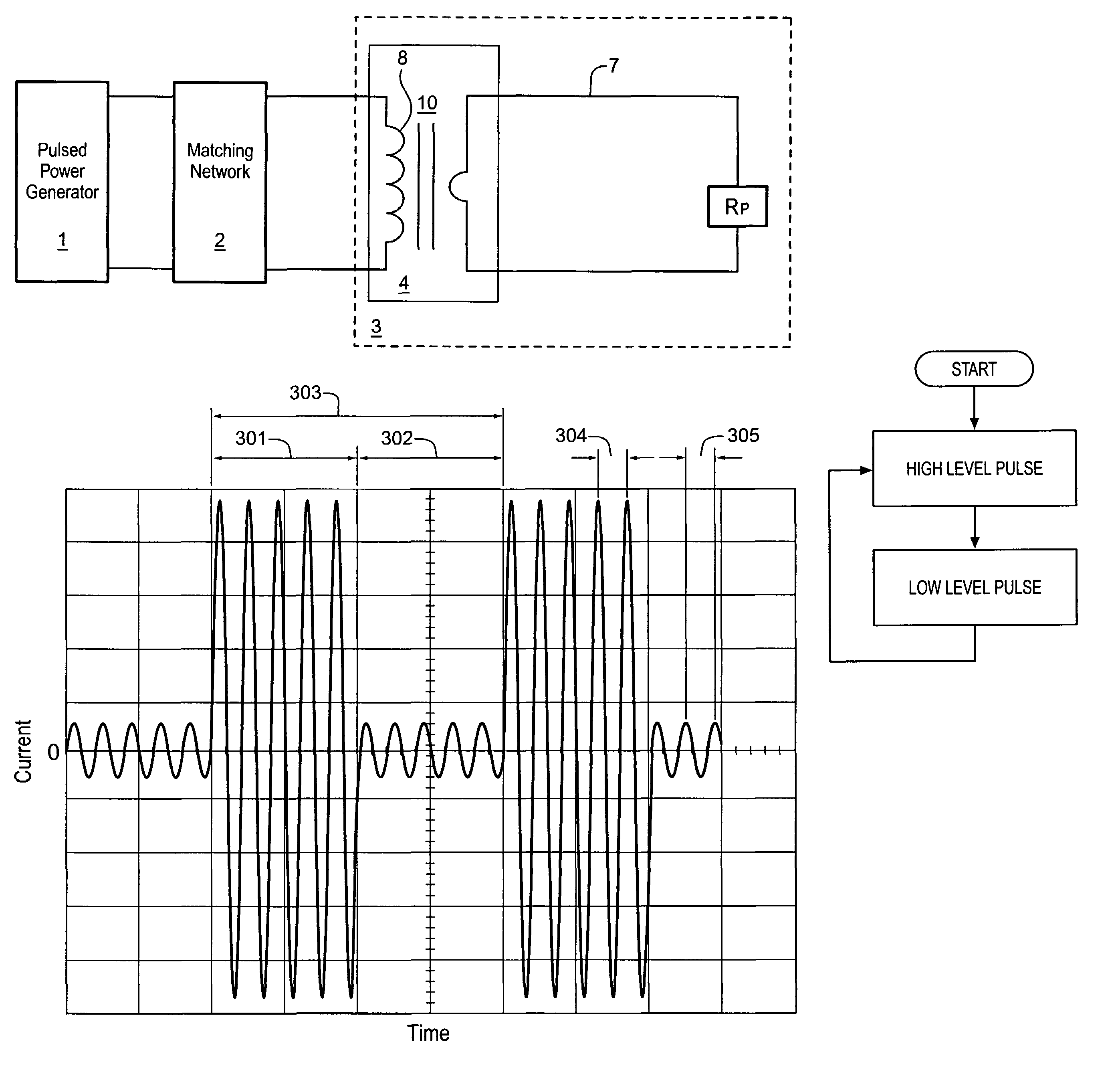
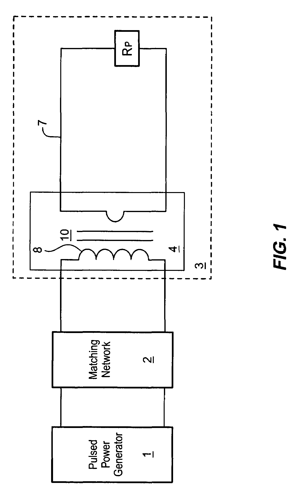
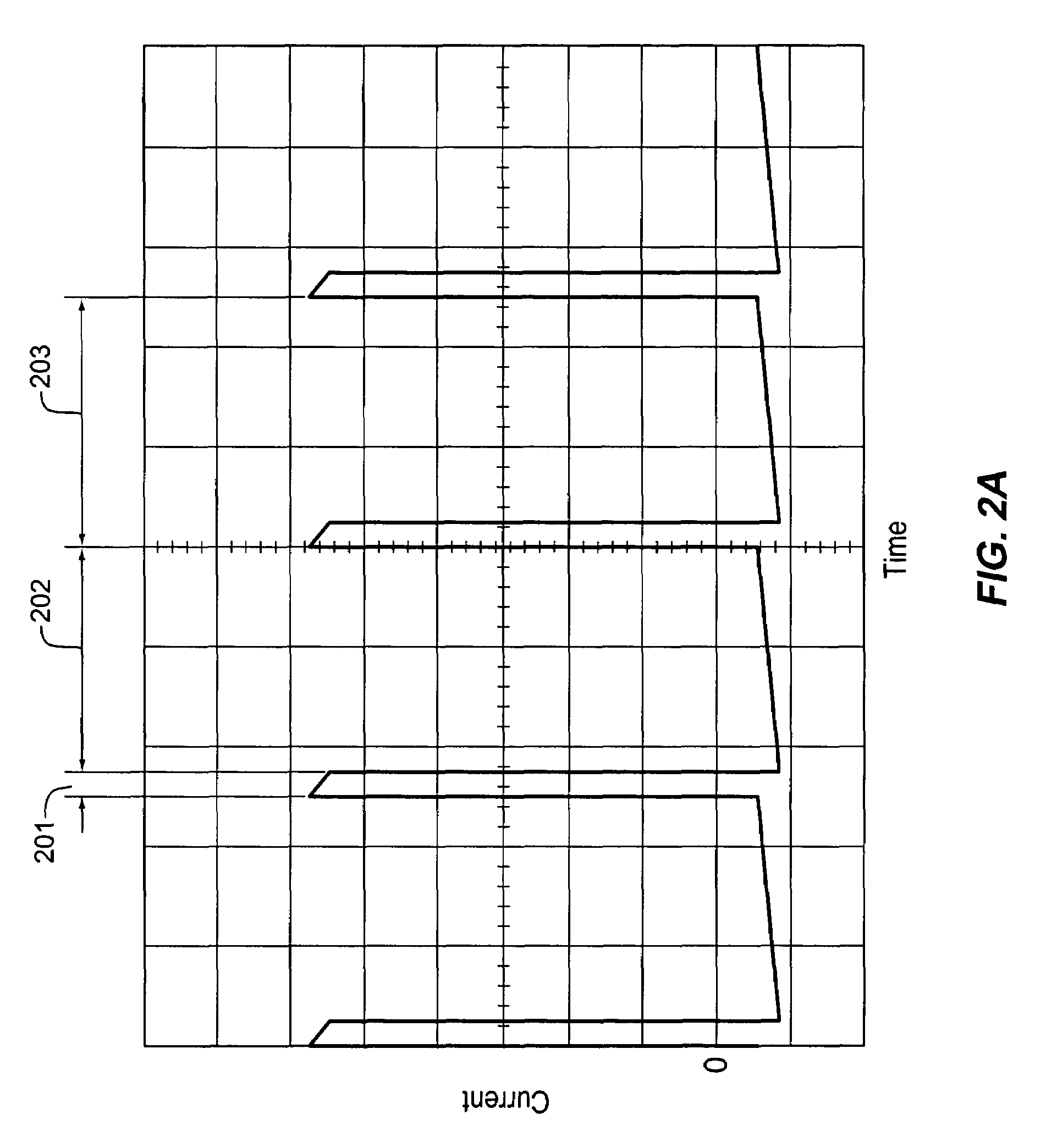
[0017]Embodiments of the invention apply pulsed power to an inductively coupled plasma chamber. The excitation consists of high and low amplitude pulses, the duration of the low amplitude pulses being typically longer than that of the high amplitude pulses. Although the duration of the high amplitude pulses may be relatively short, the plasma reaction rates are greatly enhanced beyond their value in a CW discharge of the same average power due to their exponential dependence on electron temperature. At the same time, the longer, low-amplitude intervals between the high amplitude pulses reduce the total power that must be removed from the walls. Dissociation, excitation and ionization of the feeding gas are accordingly decoupled from power deposition on the plasma chamber walls. As a consequence, the gas is efficiently dissociated or ionized while the power dissipated in the form of heat is kept low as compared to a CW mode plasma chamber.

[0018]Overview

[0019]As shown in the example a...


PUM

PropertyMeasurementUnit
Temperatureaaaaaaaaaa
Timeaaaaaaaaaa
Poweraaaaaaaaaa

Abstract

The reaction rate of a feed gas flowed into a plasma chamber is controlled. In one embodiment a pulsed power supply repeatedly applies a high power pulse to the plasma chamber to increase the reaction rate of plasma within the chamber, and applies a low power pulse between applications of the high power pulses.

Description

BACKGROUND[0001]1. Field[0002]The present invention relates to the field of plasma sources for fabrication, pollution abatement, and cleaning processes. More specifically, the present invention relates to exciting the plasma of an inductively-coupled plasma source using pulsed power.[0003]2. Description of the Related Art[0004]Plasmas are typically generated in specially built chambers. Such plasma chambers can be used for gas dissociation in etching, implantation, deposition, or cleaning processes for semiconductor and micro-machining fabrication chambers. The plasma can also be used for materials processing, production of activated gases, pollutant abatement and other applications. In some applications, the plasma is generated from oxygen, argon and fluorinated gases by driving a continuous RF (Radio Frequency) current through the plasma. In such devices, the plasma is electromagnetically coupled to an excitation coil through either the air or a magnetic core. Since the excitation...

Claims


Application Information

Patent Timeline
IPC IPC(8): C23F1/02C23C16/00H01J7/24H01J
CPCH01J37/321H01J37/32146
Inventor GONZALEZ, JUAN JOSETOMASEL, FERNANDO GUSTAVOSHABALIN, ANDREW
Owner AES GLOBAL HLDG PTE LTD
Why Eureka
Try Eureka