Rotary anode type X-ray tube

a rotary anode and x-ray tube technology, applied in the direction of x-ray tubes, sliding contact bearings, bearing cooling, etc., can solve the problems of inability to achieve adequate heat transfer effect, disturbance of enhancement of heat transfer effect, and inability to maintain stable bearing operation, etc., to achieve the effect of improving the cooling efficiency of the anode targ

Inactive Publication Date: 2006-10-24
TOSHIBA ELECTRON TUBE & DEVICES
View PDF25 Cites 24 Cited by
  • Summary
  • Abstract
  • Description
  • Claims
  • Application Information

AI Technical Summary

Benefits of technology

[0023]In the third rotary anode type X-ray tube of the invention, the heat transfer promoter is connected to the outer surface of the rotary body. Therefore, the heat of the anode target is transferred to the rotary body through the heat transfer promoter, and the heat can be transferred from a large area of the rotary body to the stationary body. Thus, the effective contact area between the stationary body and the cooling medium increases, and the cooling efficiency of the anode target can be improved.

Problems solved by technology

As a result, there is a problem that the bearing-forming material and the liquid metal lubricant react to each other to make the bearing surface rough or the bearing gap size is varied by the reaction product.
Such a problem has an adverse effect on the bearing operation, and the bearing operation cannot be maintained stably.
Such a coupling structure has high heat resistance, and an adequate heat transfer effect cannot be obtained.
In such a case, it is necessary to design considering variations in temperature, and enhancement of the heat transfer effect is disturbed.
Then, the effective contact area cannot be made adequately large, resulting in degradation of the operation characteristics of the bearing section.

Method used


Image

  • Rotary anode type X-ray tube
  • Rotary anode type X-ray tube
  • Rotary anode type X-ray tube

Examples


first embodiment

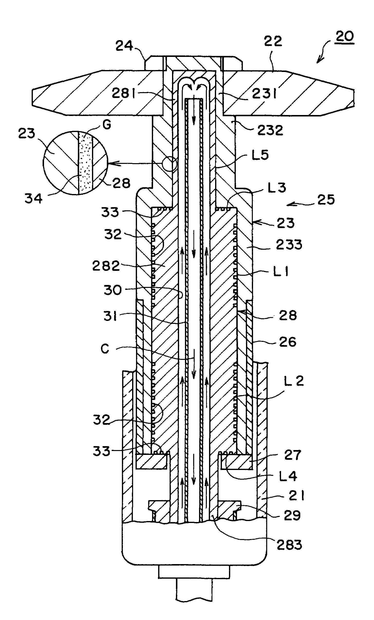
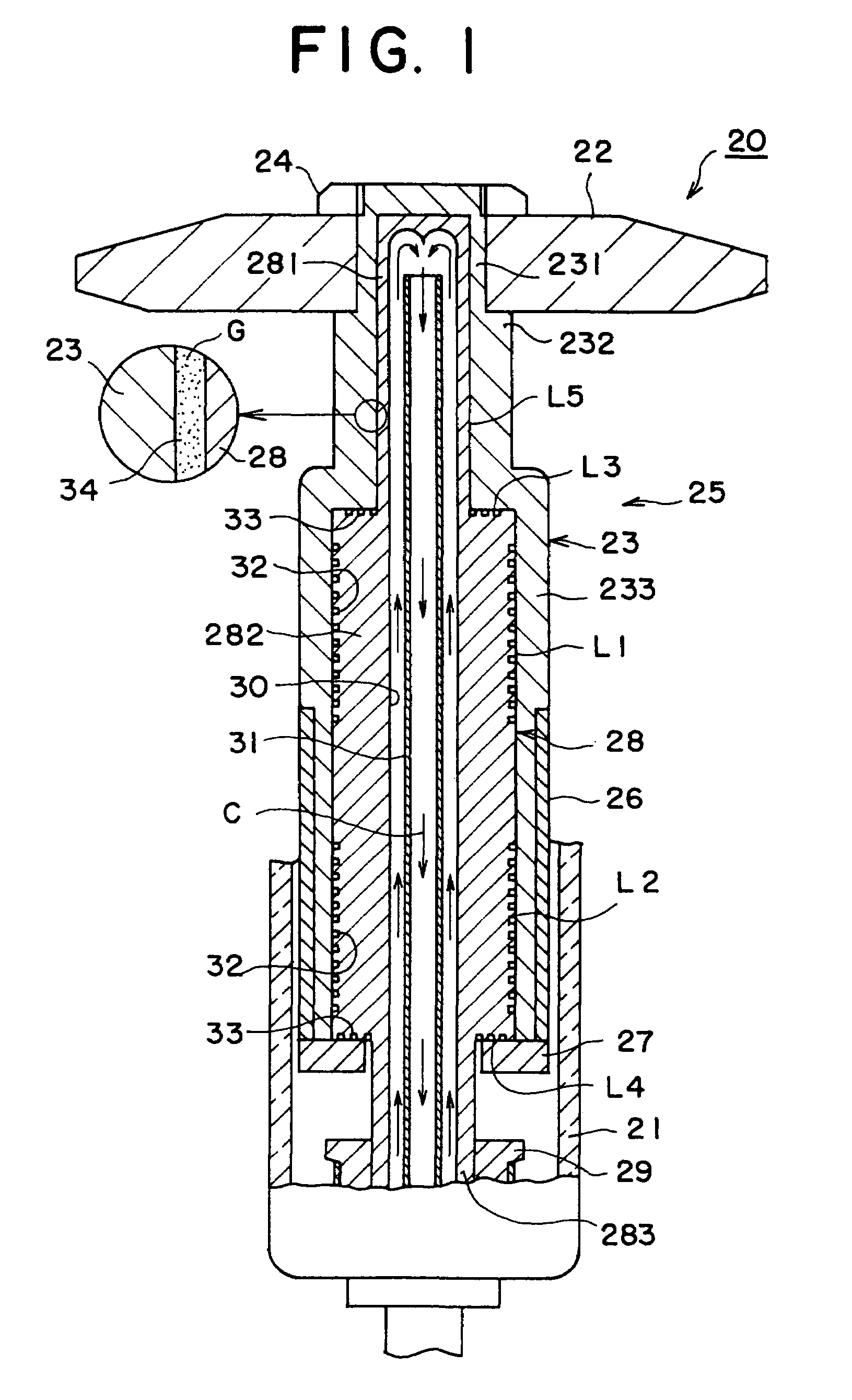
[0049]First, embodiments of the rotary anode type X-ray tube according to a first aspect of the invention will be described. FIG. 1 is a vertical sectional diagram showing a structure of the main part of the rotary anode type X-ray tube according to the first aspect of the invention. A rotary anode type X-ray tube 20 shown in FIG. 1 has, for example, a glass vacuum vessel 21. The vacuum vessel 21 shown in FIG. 1 is its part. A disk-shape anode target 22 for emitting X-rays is disposed in the vacuum vessel 21. The anode target 22 is formed of a heavy metal or the like.

[0050]The anode target 22 is fixed to the outer peripheral surface of a cylindrical rotary body 23 of a high melting-point metal with a nut 24. The rotary body 23 configures a rotating portion of a rotating mechanism 25 for rotatably supporting the anode target 22. The rotary body 23 has a first section 231 located on the top, a second section 232 having an outside diameter larger than that of the first section and loca...

second embodiment

[0070]In the rotary anode type X-ray tube 20 of the second embodiment, the bearing surfaces of the bearing areas L1 to L4 are formed of a metal material mainly consisting of iron. The metal material mainly consisting of iron can be fabricated with ease, and the bearing can be produced with high accuracy. And, the metal mainly consisting of iron is a ferromagnetic material, so that an efficiency of magnetic connection with the rotating magnetic field can be improved. Forming a ceramic film of titanium nitride or the like on the non-bearing surface of the non-bearing area L5 can further enhance erosion resistance against the liquid metal lubricant.

[0071]Then, a third embodiment of the rotary anode type X-ray tube according to the first aspect of the invention will be described with reference to FIG. 3. In FIG. 3, same numerals are used to denote same parts in FIG. 1 and FIG. 2, and a repeated description of those portions is partially omitted. In the rotary anode type X-ray tube 20 of...

fourth embodiment

[0078]In the rotary anode type X-ray tube 20 the non-bearing area L5 is in a shorter distance (spatial distance) from the anode target 22 than the bearing areas L1 to L4. In other words, the non-bearing area L5 is located where a time for heat transfer from the anode target 22 is shorter as compared with the bearing areas L1 to L4. Therefore, heat is mainly transferred from the rotary body 23 to the stationary body 28 through the non-bearing area L5. Therefore, the quantity of heat transferred through the bearing areas L1 to L4 is decreased, and the bearing areas L1 to L4 are suppressed from having a temperature increase. As a result, the bearing surface roughness and a change in bearing gap size are decreased, and a stable bearing operation can be maintained.

[0079]Besides, according to the structure of the fourth embodiment described above, the stationary body 28 is fixed to the vacuum vessel 21 at two upper and lower portions, and the bearing areas L1 to L4 are disposed on one si...


PUM


Abstract

An anode target is roratably supported by a rotating mechanism having a rotary body and a staionary body. A fitted portion between the rotary body and the stationary body is formed of bearing areas having dynamic pressure type sliding bearings and a non-bearing area having a clearance between the rotary body and the stationary body larger than that in the bearing areas. The rotary body facing the non-bearing area is positioned where a time for heat transfer from the anode target is shorter than the rotary body facing the bearing areas. Thus, the characteristics of heat radiation from the anode target can be improved, and a stable bearing operation can be maintained.

Description

CROSS-REFERENCE TO RELATED APPLICATIONS[0001]This application is the National Phase of International Application No. PCT / JP02 / 08699 filed Aug. 29, 2002, which designated the U.S. and was published on Mar. 6, 2003 as International Publication No. WO 03 / 019610 A1, which is based upon and claims the benefit of priority from prior Japanese Patent Application Nos. 2001-259087, filed Aug. 29, 2001, 2001-264281, filed Aug. 31, 2001, and 2002-018592, filed Jan. 28, 2002, the entire contents all of which are incorporated herein by reference.TECHNICAL FIELD[0002]The present invention relates to a rotary anode type X-ray tube using dynamic pressure type sliding bearings.BACKGROUND ART[0003]The rotary anode type X-ray tube has a structure that an anode target for radiating X-rays is rotatably supported by a rotating mechanism, and an electron beam is emitted to the anode target rotating at a high speed to irradiate the X-rays from the anode target. The rotating mechanism for supporting the anod...

Claims


Application Information

Patent Timeline
Patent Type & Authority Patents(United States)
IPC IPC(8): H01J35/10F16C17/10F16C33/10
CPCF16C17/026F16C17/107F16C33/107F16C37/00H01J35/10H01J35/106H01J2235/1287H01J35/104
Inventor ANNO, HIDEROSAITO, SHIN
Owner TOSHIBA ELECTRON TUBE & DEVICES
Why Eureka
Try Eureka