Failure analysis vehicle for yield enhancement with self test at speed burnin capability for reliability testing
a failure analysis and reliability testing technology, applied in the direction of testing/monitoring control systems, instruments, semiconductor/solid-state device testing/measurement, etc., can solve the problems of failure analysis of some integrated circuits that may be very time-consuming, and may take days or even weeks to isola
- Summary
- Abstract
- Description
- Claims
- Application Information
AI Technical Summary
Benefits of technology
Problems solved by technology
Method used
Image
Examples
embodiment 100
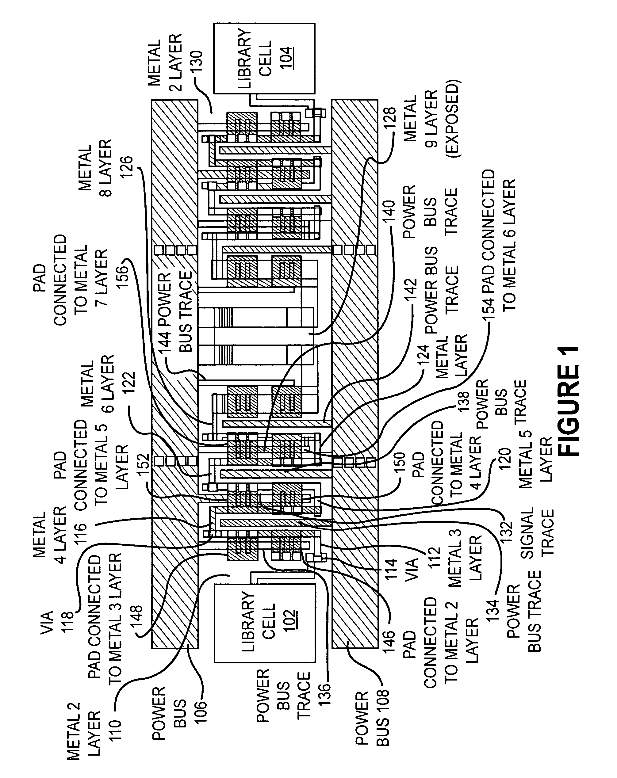
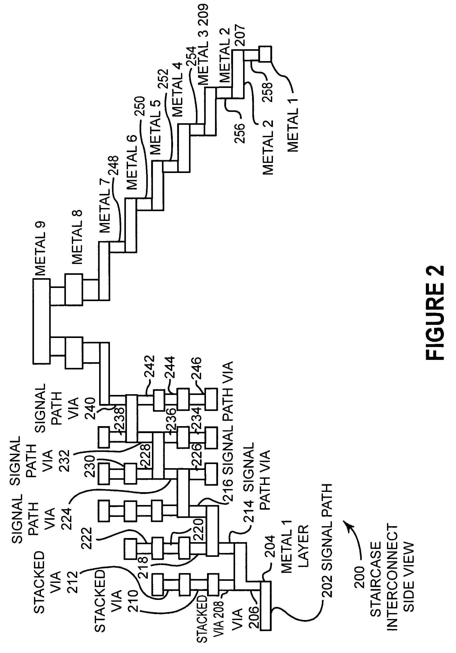
[0039]FIG. 1 illustrates an embodiment 100 of a staircase interconnect between two library cells 102 and 104 of an integrated circuit. Two power busses, 106 and 108, supply power to the cells, 102 and 104. The signal trace leaving cell 102 begins on the metal 2 layer 110 and transfers to the metal 3 layer 112 with the via 114. The signal trace then transfers to the metal 4 layer 116 with the via 118. The signal trace continues to metal 5 layer 120, metal 6 layer 122, metal 7 layer 124, and metal 8 layer 126 in a serpentine fashion. The signal trace continues to metal 9 layer 128. The serpentine pattern is repeated in a similar fashion from metal 9 layer 128 to metal 2 layer 130 and into the second library cell 104.
[0040]Within each serpentine pattern, a trace from a power bus is placed in close proximity. For example, on the metal 4 layer 116, the signal trace 132 is in close proximity to the trace 134 that is connected to the power bus 108. In a similar fashion, power bus traces 13...
embodiment 300
[0051]FIG. 3 illustrates an embodiment 300 for a unit delay schematic. The data in 302 passes through a circuit to the data out 304. The circuit comprises a buffer 306, a staircase of vias 308, a NOR gate 310, a second staircase 312, a NAND gate 314, a third staircase 316, an inverter 318, and a fourth staircase 319. The power bus comprises VDD 320 and VCC 322, which are connected to the NOR 310 and NAND 314 so that a positive signal is transmitted through the circuit. The time that is taken for the signal to propagate through the circuit can be known.
[0052]In a typical embodiment, the circuit 300 may be connected end to end many times, possibly hundreds or thousands of times in a single integrated circuit. The unit delay circuit 300 may be used in several different useful embodiments.
embodiment 400
[0053]FIG. 4 illustrates an embodiment 400 of a physical layout of the unit delay cell illustrated in FIG. 3. The circuit comprises the buffer 406, a first staircase 408, a NOR gate 410, a second staircase 412, a NAND gate 414, a third staircase 416, an inverter 418, and a fourth staircase 419. The VDD 420 and VCC 422 power busses are also shown.
[0054]The cells may be arranged such that the power busses are aligned. This arrangement allows easy mechanical cross sectioning of the circuits to inspect problem areas. In the cross sections, known good traces may be compared to suspected bad traces because of the repeating pattern of the embodiment 400.
PUM
 Abstract
Description
Claims
Application Information
 - R&D
- Intellectual Property
- Life Sciences
- Materials
- Tech Scout
- Unparalleled Data Quality
- Higher Quality Content
- 60% Fewer Hallucinations
Browse by: Latest US Patents, China's latest patents, Technical Efficacy Thesaurus, Application Domain, Technology Topic, Popular Technical Reports.
© 2025 PatSnap. All rights reserved.Legal|Privacy policy|Modern Slavery Act Transparency Statement|Sitemap|About US| Contact US: help@patsnap.com


