
Methods for forming low resistivity, ultrashallow junctions with low damage

a technology of ultrashallow junctions and resistivity, which is applied in the direction of coatings, metallic material coating processes, chemical vapor deposition coatings, etc., can solve the problems of low implant energy, inefficient operation of conventional ion implanters at very low implant energies, and other problems produced by the annealing process

Inactive Publication Date: 2006-11-14
VARIAN SEMICON EQUIP ASSOC INC
View PDF33 Cites 15 Cited by
  • Summary
  • Abstract
  • Description
  • Claims
  • Application Information

AI Technical Summary

Benefits of technology

The invention relates to a method for creating shallow junctions in a semiconductor wafer by introducing dopant materials that form charge carrier complexes. These complexes are stable and can be controlled to achieve low sheet resistance, which leads to improved conductivity. The method involves short-time thermal processing of the doped surface layer, which can be done using flash rapid thermal processing or other techniques. The dopant materials can be introduced into the shallow surface layer by ion implantation or plasma doping. The technical effect of this invention is to provide a more efficient and effective method for creating shallow junctions in semiconductor wafers.

Problems solved by technology

However, the annealing process that is used for activation of the implanted dopant material causes the dopant material to diffuse from the implanted region of the semiconductor wafer.
In addition, conventional ion implanters typically operate inefficiently at very low implant energies.
However, as noted above, other problems are produced by the annealing process.
These factors have presented difficulties in achieving ultrashallow junctions which have low sheet resistance and low damage.

Method used


Image

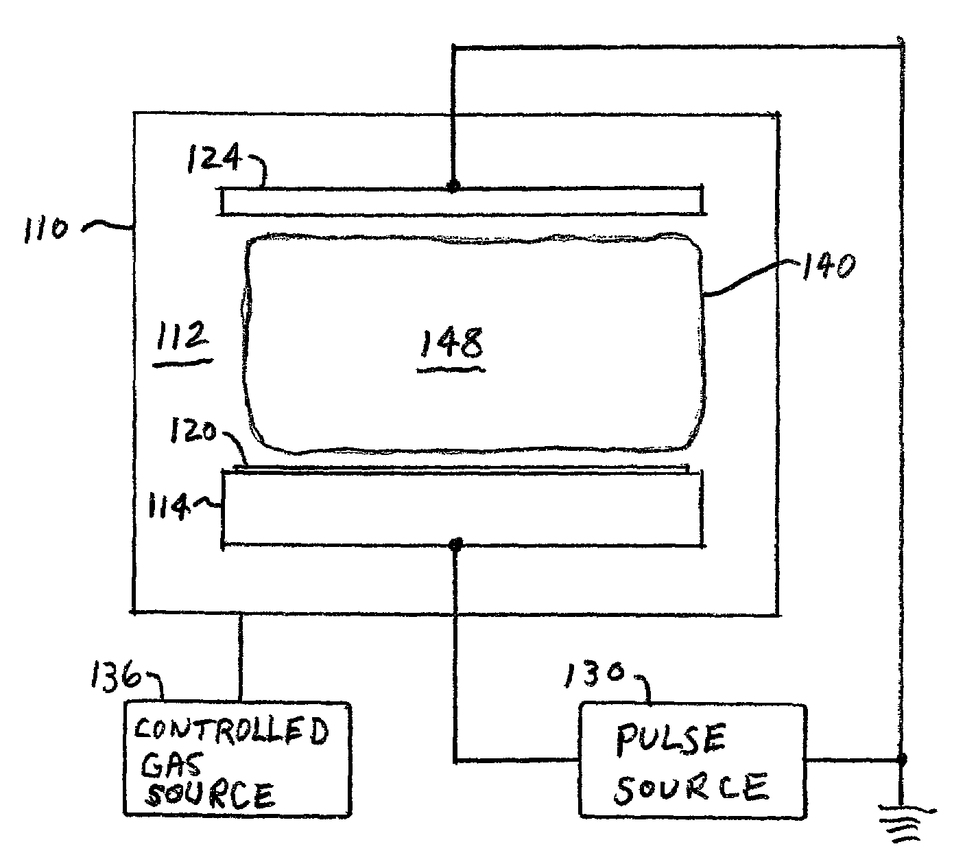
  • Methods for forming low resistivity, ultrashallow junctions with low damage
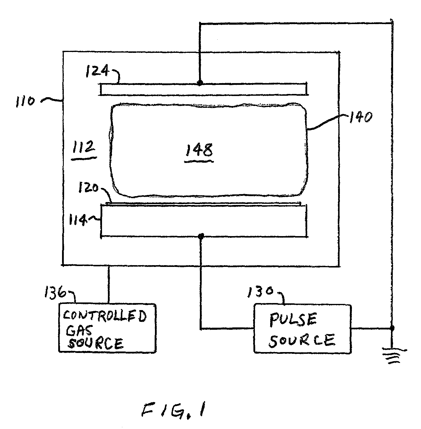
  • Methods for forming low resistivity, ultrashallow junctions with low damage
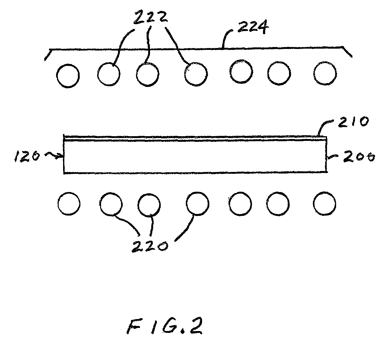
  • Methods for forming low resistivity, ultrashallow junctions with low damage

Examples


Embodiment Construction

[0021]According to an aspect of the invention, methods are provided for forming ultrashallow junctions in semiconductor wafers. The methods involve the formation of charge carrier complexes which produce at least two charge carriers per complex. Each charge carrier complex includes two or more atoms which are chemically bonded together. Examples include boron bonded to silicon, boron bonded to germanium, and boron bonded to fluorine. The charge carrier complex may include an electron-hole pair bound to the chemically-bonded atoms. At room temperature, the electron-hole pairs are dissociated from the complexes and are available to participate in electrical conduction. An example of a charge carrier complex is the exciton complex described, for example, by R. Knox in Theory of Excitons, Academic Press, New York (1963).

[0022]The charge carrier complexes may be formed by introducing into a shallow surface layer of the semiconductor wafer two dopant species which can chemically bond or o...


PUM

PropertyMeasurementUnit
temperatureaaaaaaaaaa

Abstract

Methods for forming ultrashallow junctions in semiconductor wafers include introducing into a shallow surface layer of a semiconductor wafer a dopant material that is selected to form charge carrier complexes which produce at least two charge carriers per complex, and short-time thermal processing of the doped surface layer to form the charge carrier complexes. The short-time thermal processing step may be implemented as flash rapid thermal processing of the doped surface layer, sub-melt laser processing of the doped surface layer, or RF or microwave annealing of the doped surface layer.

Description

FIELD OF THE INVENTION[0001]This invention relates to methods for forming ultrashallow junctions in semiconductor wafers and, more particularly, to methods for forming ultrashallow junctions having low sheet resistance and low damage by the formation and stabilization of charge carrier complexes in a shallow surface layer of the semiconductor wafer.BACKGROUND OF THE INVENTION[0002]A well-known trend in the semiconductor industry is toward smaller, higher speed devices. In particular, both the lateral dimensions and the depth of features in semiconductor devices are decreasing. State of the art semiconductor devices require junction depths less than 1,000 angstroms and may eventually require junction depths on the order of 200 angstroms or less.[0003]Ion implantation is a standard technique for introducing conductivity-altering dopant materials into semiconductor wafers. In a conventional ion implantation system, known as a beamline ion implanter, a desired dopant material is ionized...

Claims


Application Information

Patent Timeline
Patent Type & Authority Patents(United States)
IPC IPC(8): H01L21/26C23C16/00H01L21/42H01L21/265H01L21/268H01L21/324
CPCH01L21/26513H01L21/324H01L21/268H01L21/2658H01L21/265
Inventor DOWNEY, DANIEL F.
Owner VARIAN SEMICON EQUIP ASSOC INC
Learn More