Pressure sensor

a capacitive pressure sensor and capacitive technology, applied in the direction of variable capacitors, liquid/fluent solid measurement, instruments, etc., can solve the problems of unsuitable mass production, lack of long-term reliability, and resistance to higher pressures, and achieve long-term stable sealing effect, excellent mass productivity, and sufficient resistance to maintain sealing

Inactive Publication Date: 2006-11-14
ALPS ALPINE CO LTD
View PDF12 Cites 26 Cited by
  • Summary
  • Abstract
  • Description
  • Claims
  • Application Information

AI Technical Summary

Benefits of technology

[0015]To solve the above problems, the present invention aims at providing a pressure sensor in which the overall vacuum sealing surfaces of a silicon substrate and a glass substrate are sealed by anode bonding to attain excellent reliability and resistance to higher pressures and to enable a process to be carried out with excellent mass productivity. In addition, the present invention aims at providing a compact pressure sensor including a diaphragm with a precisely controlled thickness and having small variations in properties.
[0019]The pressure sensor having the above structure, in which the overall vacuum sealing surfaces of the silicon substrate and glass substrate are sealed by anode bonding, has a long-term stable sealing effect and sufficient resistance for maintaining sealing at higher pressures, and can be produced by a process with excellent mass productivity. In addition, the present invention can provide a compact pressure sensor including a diaphragm with a precisely controlled thickness and having small variations in properties.

Problems solved by technology

The clamping structure using a resin as shown in Japanese Unexamined Patent Application Publication No. 07-209117 and the sealing methods using a metal or oxide film as shown in Japanese Unexamined Patent Application Publication No. 08-097438 and Japanese Unexamined Patent Application Publication No. 11-284204, however, lack long-term reliability and have a problem in terms of resistance to higher pressures.
In particular, the sealing structures in Japanese Unexamined Patent Application Publication No. 07-209117 and Japanese Unexamined Patent Application Publication No. 08-097438 also have a problem in that they involve a complicated process including the step of depositing a part of a lead portion and are therefore unsuitable for mass production.
In addition, the sealing structure using a silicon cover plate as disclosed in Japanese Unexamined Patent Application Publication No. 04-009727 further involves the step of forming the cover over a through hole, and also has difficulty in reducing the size of devices because this structure requires a space for attaching the cover plate.

Method used


Image

  • Pressure sensor
  • Pressure sensor
  • Pressure sensor

Examples


first embodiment

[0030][First Embodiment]

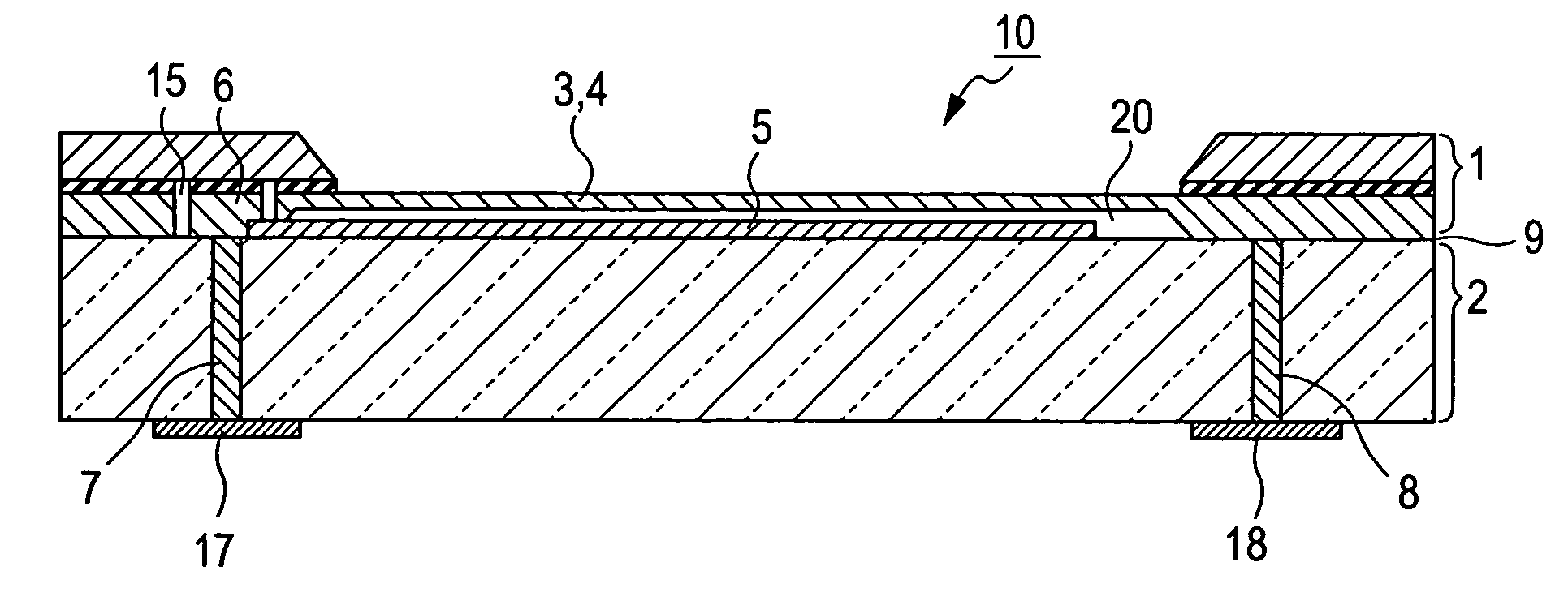
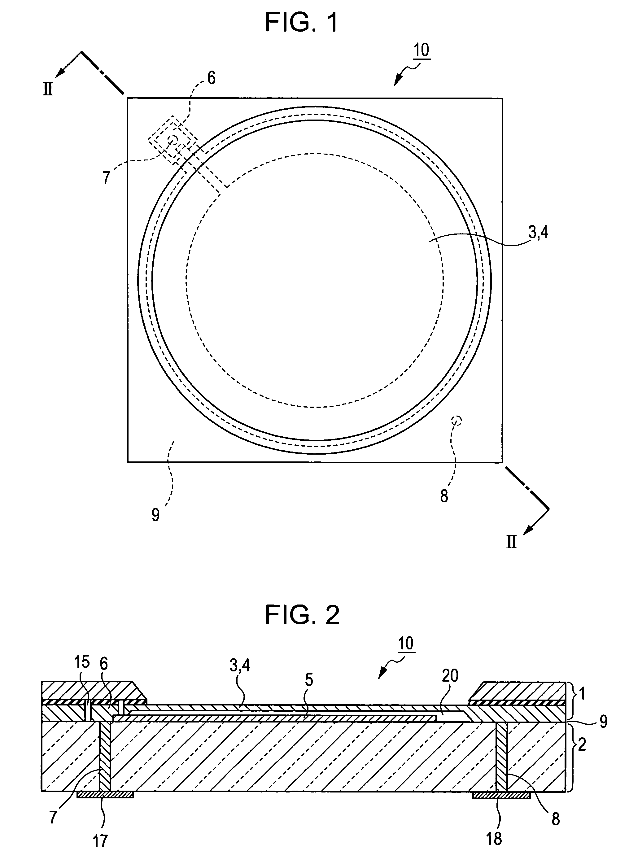
[0031]FIG. 1 is a plan view of a pressure sensor according to a first embodiment of the present invention. FIG. 2 is a sectional view, taken along line II—II, of the pressure sensor in FIG. 1.

[0032]In FIG. 1, a pressure-sensitive diaphragm portion 3 made of a silicon substrate is disposed in the center of a pressure sensor 10. A first electrode (diaphragm electrode) 4 is formed on the pressure-sensitive diaphragm portion 3, namely the silicon substrate. An output electrode 7 for a second electrode 5 (sensing electrode) and an output electrode 8 for the first electrode 4 are formed in a diagonal line with the pressure-sensitive diaphragm portion 3 disposed therebetween. A silicon island 6 is provided around the output electrode 7 for the second electrode 5. A silicon-on-insulator (SOI) substrate 1 and a glass substrate 2 are bonded, except for the pressure-sensitive diaphragm portion 3 and the silicon island 6, by a known method, namely anode bonding, so as to...

second embodiment

[0040][Second Embodiment]

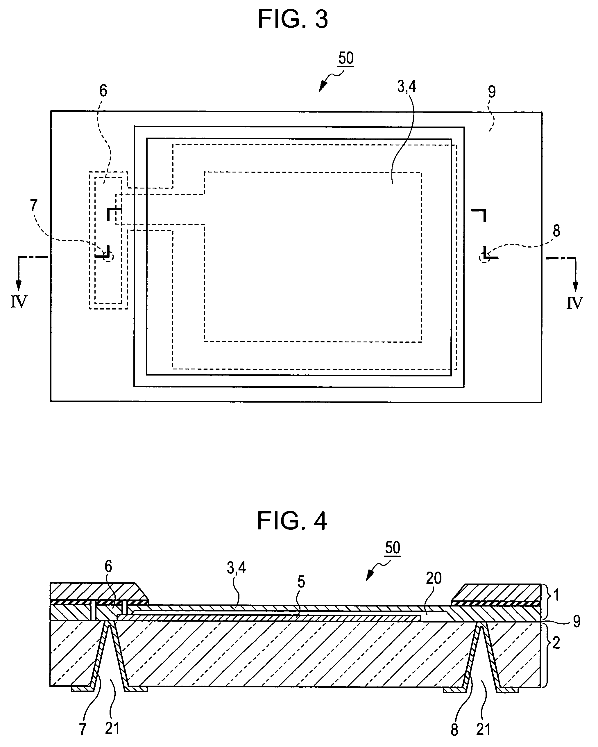
[0041]FIG. 3 is a plan view of a pressure sensor according to a second embodiment of the present invention. FIG. 4 is a sectional view, taken along line IV—IV, of the pressure sensor in FIG. 3.

[0042]A pressure sensor 50 according to the second embodiment of the present invention in FIGS. 3 and 4 is different from the pressure sensor 10 according to the first embodiment of the present invention in FIGS. 1 and 2 in that the pressure-sensitive diaphragm portion 3 and the silicon island 6 are rectangular and that the output electrodes 7 and 8 formed in the glass substrate 2 are conical in cross section. No detailed description is given below because the structures and features of the individual parts are the same as those in the first embodiment.

[0043]The output electrodes 7 and 8 that are conical in cross section are advantageous in that deep through holes can be readily formed by sandblasting.

[0044]The pressure-sensitive diaphragm portion 3 may be circular or ...


PUM

PropertyMeasurementUnit
voltageaaaaaaaaaa
pressureaaaaaaaaaa
capacitanceaaaaaaaaaa

Abstract

A pressure sensor includes a silicon-on-insulator (SOI) substrate, a glass substrate bonded to the SOI substrate by anode bonding, a silicon island formed on a part of a silicon layer of the SOI substrate and surrounded by a groove extending to an insulating layer of the SOI substrate, a through hole formed in the glass substrate, and an output electrode that is made of a conductive material, is disposed inside the through hole, and is electrically connected to an electrode formed on the glass substrate via the silicon island.

Description

BACKGROUND OF THE INVENTION[0001]1. Field of the Invention[0002]The present invention relates to the structures of capacitive pressure sensors requiring hermetic sealing.[0003]2. Description of the Related Art[0004]A known capacitive pressure sensor for measuring absolute pressure includes a silicon substrate and a glass substrate that are bonded so as to seal a microgap therebetween, thereby forming a reference pressure chamber. The silicon substrate has a pressure-sensitive diaphragm portion for sensing the pressure to be measured.[0005]An electrode is formed on the pressure-sensitive diaphragm portion by diffusing an impurity using semiconductor manufacturing technology while another electrode is formed on the glass substrate by depositing a thin metal film using, for example, vapor deposition or sputtering. Leads from the two electrodes are connected to the outside via a diffusion lead and a metal lead extending between the bonding surfaces of the silicon and glass substrates. T...

Claims


Application Information

Patent Timeline
Patent Type & Authority Patents(United States)
IPC IPC(8): H01L29/84G01L9/00
CPCG01L9/0073G01L9/0042
Inventor SAKAI, SHIGEFUMIABE, MUNEMITSU
Owner ALPS ALPINE CO LTD
Why Eureka
Try Eureka