Shaft comprising a part connected thereto by welding

a technology of a shaft and a connection part, applied in the field of shafts, can solve the problems of premature fracture, reducing long-term strength, etc., and achieve the effect of restricting the introduction of hea

Inactive Publication Date: 2006-11-21
MAGNA STEYR POWERTRAIN
View PDF8 Cites 2 Cited by
  • Summary
  • Abstract
  • Description
  • Claims
  • Application Information

AI Technical Summary

Benefits of technology

[0006]According to the invention, the foregoing object is achieved wherein a welding bead starts at a starting point on the surface located perpendicular to the seating surface, leads to the fillet and then leads back to an end point on the surface located perpendicular to the seating surface. The starting and end points of the welding bead therefore lie outside the more sensitive part, generally the shaft. The starting crater and / or end crater of the welding bead does not cause any problems on the transversely located surface of the element which is subject to lower loads at least in the zone of this surface. The connecting part of these craters then lies in the fillet. The welding bead can but does not have to follow the entire circumference of the shaft; it may remain restricted to one part or a number of parts of the circumference. The favorable loading situation of a weld seam which has been disposed in a fillet of this nature allows the use of a very slender and short welding bead. As a result, and on account of the special shape of the welding bead, the introduction of heat is restricted and the shaft is not distorted.

Problems solved by technology

There are two reasons for this: firstly, heating of the shaft causes it to be distorted, which has an adverse effect on true running; secondly, cracks are formed at the start and / or end of the welding bead, reducing the long-term strength and / or leading to premature fractures.

Method used


Image

  • Shaft comprising a part connected thereto by welding
  • Shaft comprising a part connected thereto by welding
  • Shaft comprising a part connected thereto by welding

Examples


Embodiment Construction

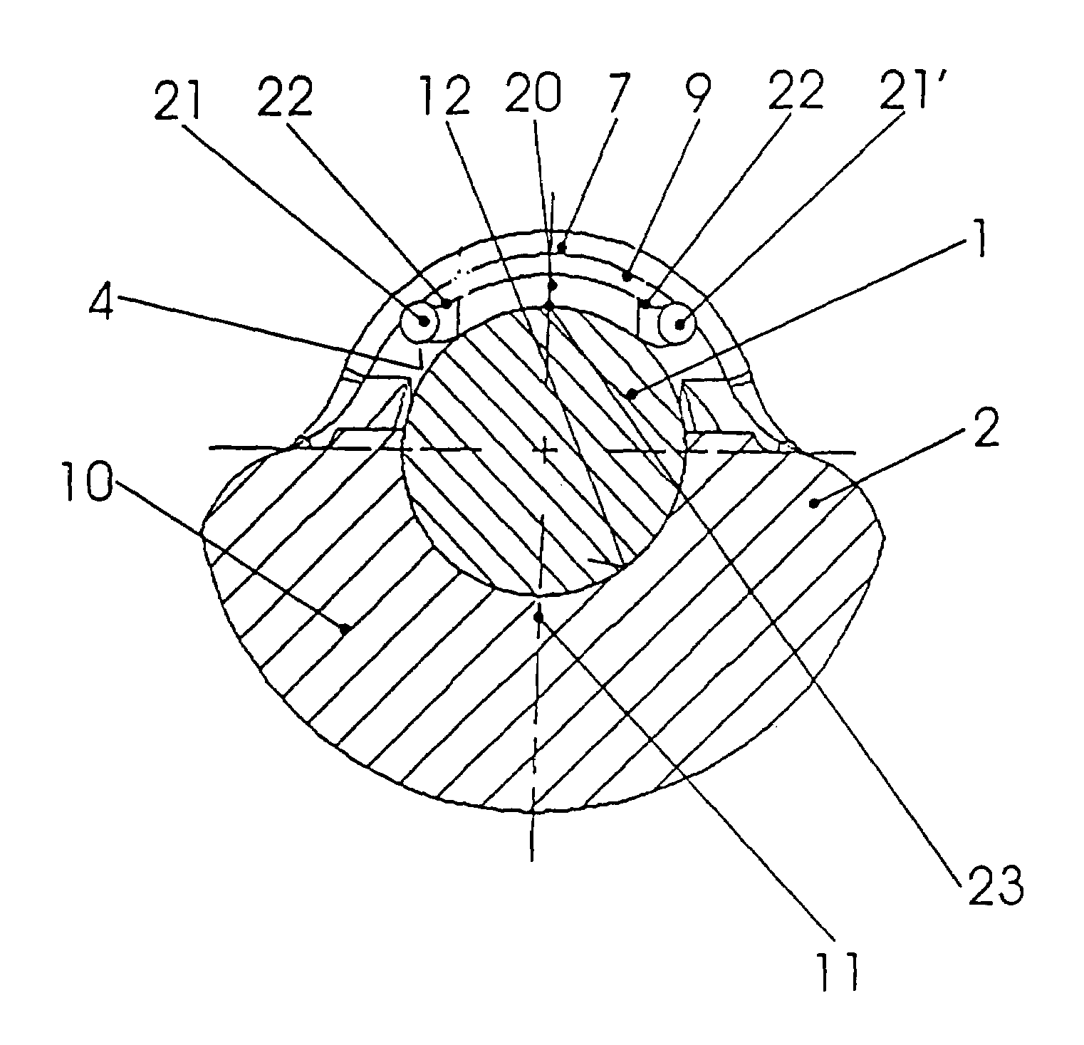
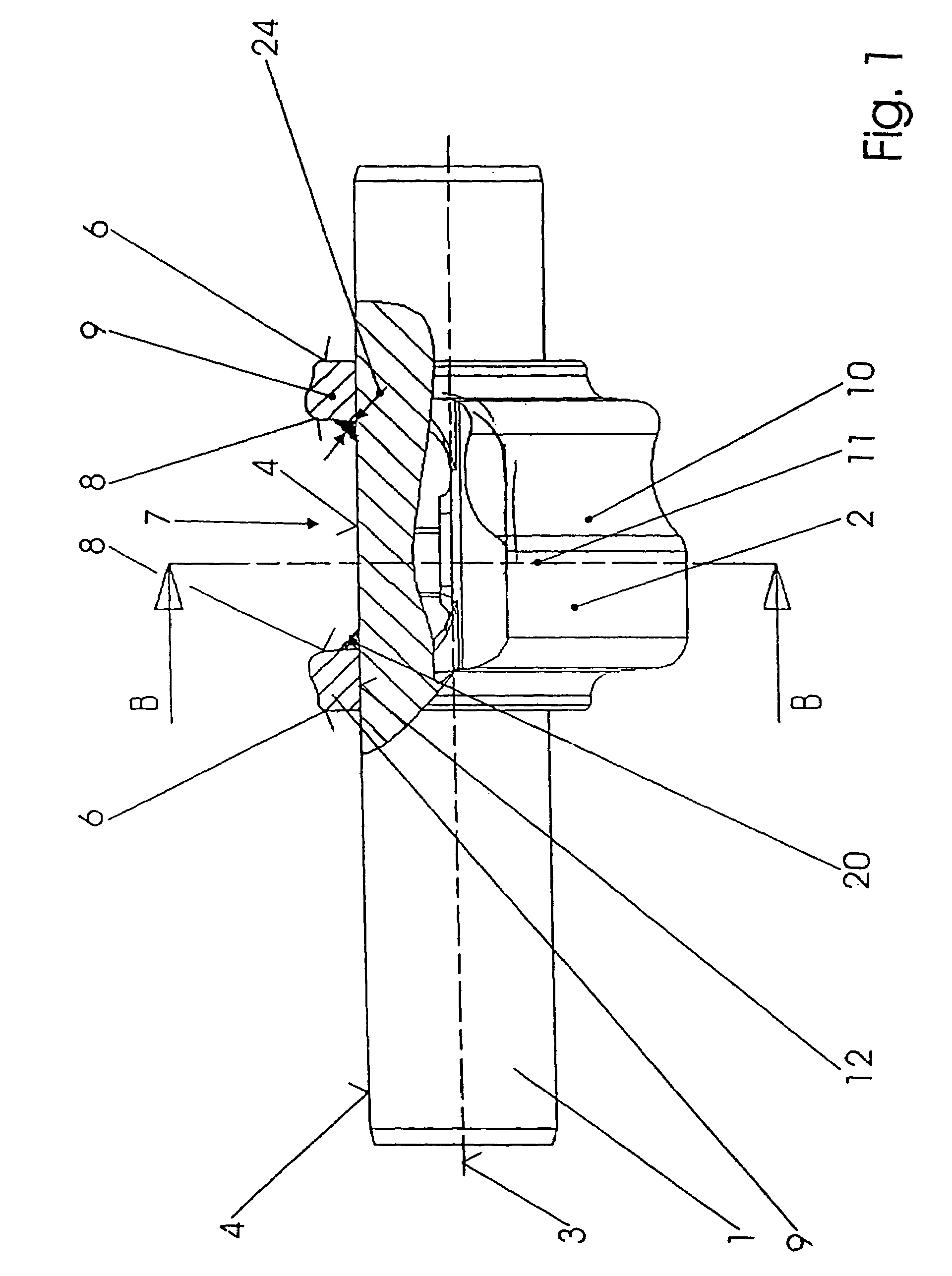
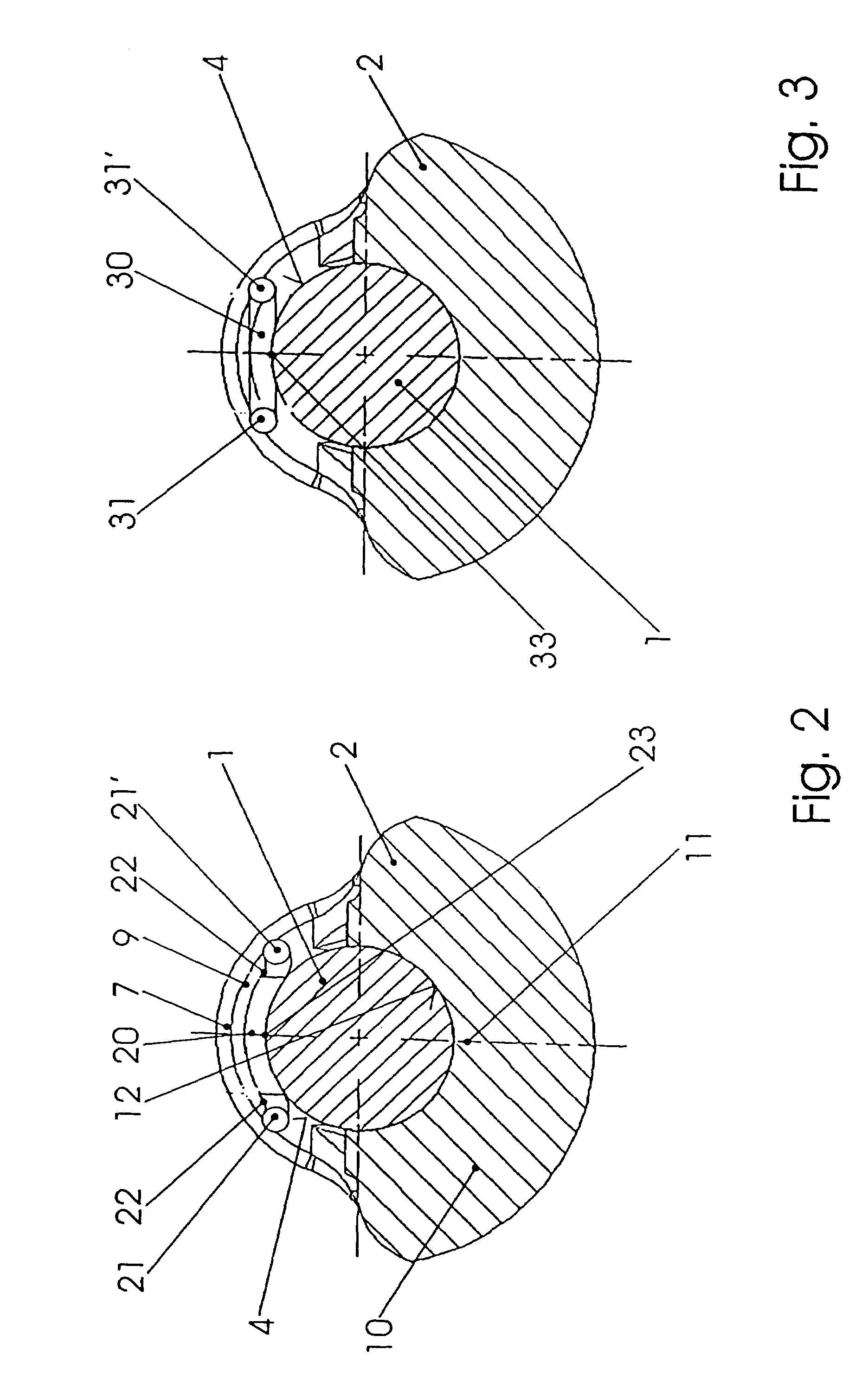
[0025]In FIG. 1 and FIG. 2, a shaft is denoted by 1, its axis of rotation is denoted by 3 and a co-rotating element secured to the shaft 1 is denoted by 2. The shaft is in this case a balancing shaft, while the co-rotating element is a balancing weight which is located on the cylindrical seating surface 4 of the shaft 1. The shaft 1 is in this case cylindrical over its entire length, but could also be stepped and increased in diameter on one side of the element.

[0026]The element 2, in this case a balancing weight, has two outer surfaces 6 and a cutout 7 extending only over part of its circumference, forming two inner end faces 8. These end faces generally lie transversely with respect to the axis 3, in this specific case normally with respect to the axis 3. In this way, a right-angled fillet is formed between the surfaces 6, 8 and the cylindrical seating face 4 of the shaft, and this fillet is a suitable location for the welding. The surfaces 6, 8 do not have to be axially normal; i...


PUM

PropertyMeasurementUnit
diameteraaaaaaaaaa
diameteraaaaaaaaaa
gravityaaaaaaaaaa

Abstract

A shaft (1) with a co-rotating element (2) which is secured to it and has a surface located perpendicular to the axis (3) of the shaft, the welding taking place in the fillet formed between the seating surface (4) of the shaft (1) and axially normal surface (6, 8) of the element. To achieve a durable join without adversely affecting true running, a welding bead (20) starts at a starting point (21) on the surface (6; 8) located perpendicular to the axis (3) of the shaft (1), leads to the fillet and then leads back to an end point (21′) on the surface (6; 8) located transversely with respect to the axis of the shaft.

Description

BACKGROUND OF THE INVENTION[0001]The invention relates to a shaft with a co-rotating element fitted and secured to it, the shaft being cylindrical at least in the region in which the element is fitted, and the element having a cylindrical seating surface and at least one surface which is located perpendicular to the seating surface, and the welding taking place in the fillet formed between the seating surface of the shaft and that surface of the element which is located perpendicular to the seating surface. The term region is to be understood as meaning the location where the element is secured and the area surrounding it in at least one longitudinal direction.[0002]The shaft may be a drive shaft, transmission shaft, crankshaft, camshaft or balancing shaft of a piston engine, and the co-rotating element may therefore be any desired flange, a wheel or gear, part of a clutch, a cam or a balancing weight. Consideration may be given in particular to shafts which run at high rotational s...

Claims


Application Information

Patent Timeline
Patent Type & Authority Patents(United States)
IPC IPC(8): F16C3/10F16C3/18B23K9/00B23K9/028B23K10/02F16D1/068
CPCB23K9/0286B23K10/02F16D1/068Y10T403/478Y10T74/2183Y10T464/50Y10T403/477F16F15/264
Inventor KEHRER, OSKAR
Owner MAGNA STEYR POWERTRAIN
Why Eureka
Try Eureka