Method and apparatus for performing model-based layout conversion for use with dipole illumination

a dipole illumination and model-based technology, applied in the field of photolithography, can solve the problems of reducing the size of the integrated circuit, the critical dimension of the corresponding mask pattern approaching the resolution limit of the optical exposure tool, and the shrinking rate of the design rule outpacing the progress of both the exposure wavelength reduction and the high-speed advancement. , to achieve the effect of simplifying the layout conversion process

Inactive Publication Date: 2006-11-21
ASML NETHERLANDS BV
View PDF10 Cites 39 Cited by
  • Summary
  • Abstract
  • Description
  • Claims
  • Application Information

AI Technical Summary

Benefits of technology

[0015]In an effort to solve the foregoing needs, it is one object of the present invention to provide a method for generating the horizontal and vertical masks for performing dipole illumination which simplifies the layout conversion process relative to the prior art techniques and allows for a more straight-forward design approach.
[0016]More specifically, the present invention relates to a method of generating complementary masks for use in a multiple-exposure lithographic imaging process. The method includes the steps of: identifying a target pattern having a plurality of features comprising horizontal and vertical edges; generating a horizontal mask based on the target pattern; generating a vertical mask based on the target pattern; performing a shielding step in which at least one of the vertical edges of the plurality of features in the target pattern is replaced by a shield in the horizontal mask, and in which at least one of the horizontal edges of the plurality of features in the target pattern is replaced by a shield in the vertical mask, where the shields have a width which is greater that the width of the corresponding feature in the target pattern; performing an assist feature placement step in which sub-resolution assist features are disposed parallel to at least one of the horizontal edges of the plurality of features in the horizontal mask, and are disposed parallel to at least one of the vertical edges of the plurality of features in the vertical mask, and performing a feature biasing step in which at least one of the horizontal edges of the plurality of features in the horizontal mask are adjusted such that the resulting feature accurately reproduces the target pattern, and at least one of the vertical edges of the plurality of features in the vertical mask are adjusted such that the resulting feature accurately reproduces the target pattern.
[0022]The method of the present invention provides important advantages over the prior art. Most importantly, instead of using a complicated hand-crafted rule-based decomposition flow, the method of the present invention allows for a simplified model-based procedure for generating the horizontal and vertical masks from the target design.
[0023]Further, the method of the present invention not only simplifies the processing flow, but it also helps to eliminate several significant problems associated with known techniques. For example, in comparison to the present invention, the known rule-based method illustrated in FIG. 2 requires the generation of a dedicated rule for each and every kind of feature to be printed. Thus, for any practical design, the set of rules that must be generated is prohibitively large. In contrast, with the method of the present invention, there is no need to build a library of rules: The table illustrated in FIG. 13 lists some of the differences between the method of the present invention and the known rule-based method.
[0024]In addition, the model-based approach of the present invention also provides shielding treatment, which more effectively handles difficult structures, such as, jogs, S-turns and U-turns. Further, the method of the present invention is capable of simultaneously converting complex logic and memory mask patterns in double dipole lithography (DDL) compatible mask layouts.

Problems solved by technology

These rules are set by processing and design limitations.
As the size of an integrated circuit is reduced and its density increases, however, the CD (critical dimension) of its corresponding mask pattern approaches the resolution limit of the optical exposure tool.
Furthermore, as the demand continues for even higher performance of semiconductor devices, the design rule shrink rate is outpacing the progress of both of the exposure wavelength reduction and the advancement of high Numerical Aperture (NA) lenses.
This factor has presented a challenge to lithographers to push optical lithography beyond the limit that was thought possible a few years ago.
However, one of the limitations associated with dipole illumination is that a single illumination only enhances resolution for features that are orthogonal to the illumination pole axis.
When utilizing dipole illumination techniques, as a result of the need to separate the horizontally and vertically oriented features, one of the challenges for the lithographer is determining how to convert the original IC design data into its horizontal or vertical pattern components and generate two masks for the dual exposure process that can take full advantage of the dipole imaging performance.
Currently known techniques for generating the horizontal and vertical masks do not always produce optimal results when attempting to generate such masks for complex structures.
For example, utilizing known techniques such as the one disclosed in the flowchart of FIG. 2, it is sometimes difficult, for example, to provide proper shielding for complex structures, such as, “jogs” (i.e., short changes in either the vertical or horizontal direction, for example, a short vertical step, between two long horizontal lines), short “S” turns and / or U-shaped patterns in the design.
Moreover, it is sometimes difficult to determine whether or not a given structure of the target design should be treated as a horizontal structure or a vertical structure when initially generating the horizontal and vertical masks.

Method used


Image

  • Method and apparatus for performing model-based layout conversion for use with dipole illumination
  • Method and apparatus for performing model-based layout conversion for use with dipole illumination
  • Method and apparatus for performing model-based layout conversion for use with dipole illumination

Examples


Embodiment Construction

[0043]As explained in more detail below, the preferred embodiment of the present invention provides a method and apparatus for generating horizontal and vertical masks for use with dipole illumination. Specifically, the method of the present invention relates to a model-based layout-conversion method for generating the horizontal and vertical masks from a target design.

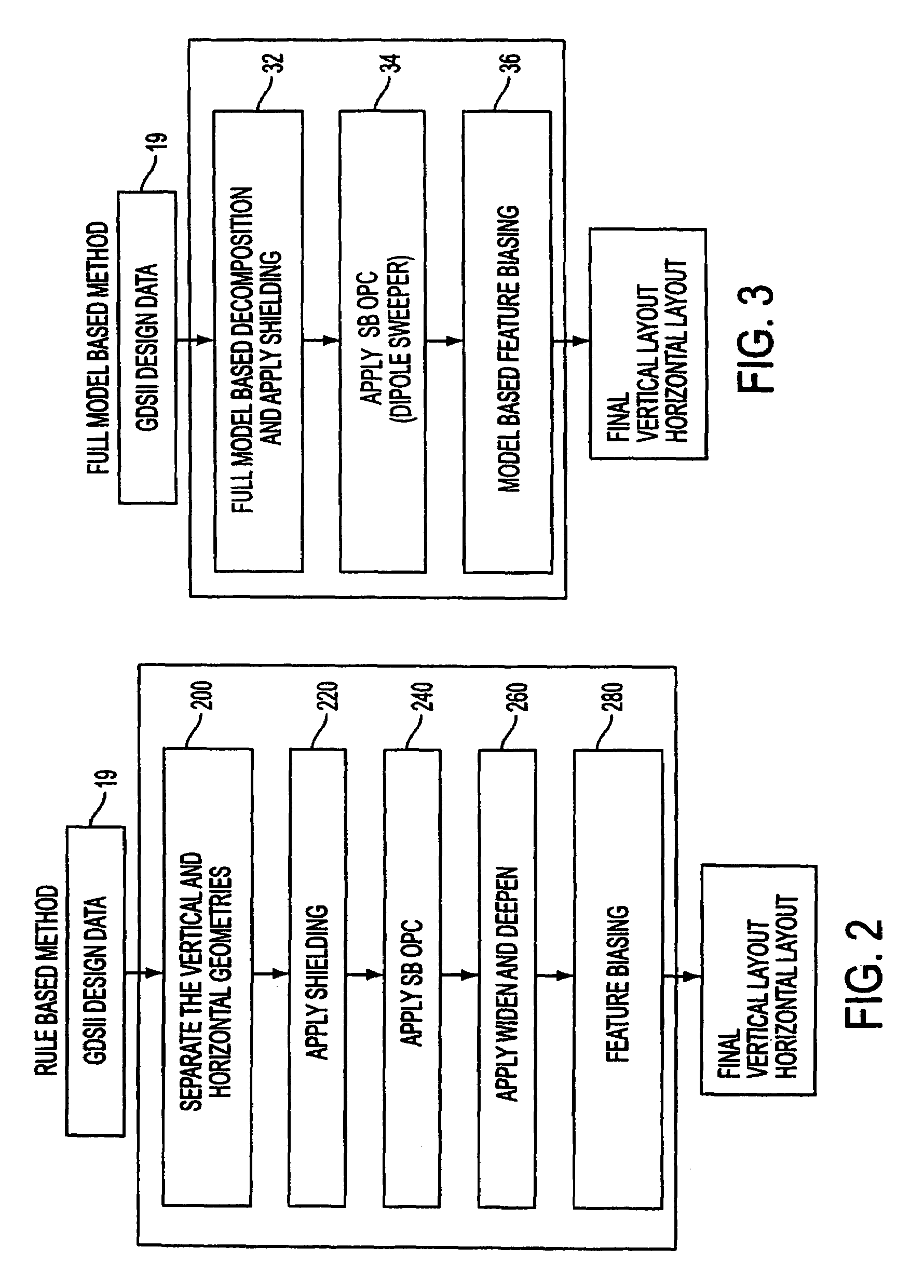
[0044]FIG. 3 is an exemplary flowchart illustrating the model-based layout-conversion method of the present invention. As is shown in FIG. 3, the model-based approach entails essentially 3 basic processing steps.

[0045]Referring to FIG. 3, the first step (Step 32) of the model-based approach comprises applying shielding utilizing a model-based OPC to the vertical edges in the target pattern so as to define the horizontal mask, and applying shielding to the horizontal edges in the target pattern so as to define the vertical mask. In other words, the starting point for both the horizontal mask and the vertical mask is th...


PUM

PropertyMeasurementUnit
widthaaaaaaaaaa
widthaaaaaaaaaa
widthaaaaaaaaaa

Abstract

A method of generating complementary masks for use in a multiple-exposure lithographic imaging process. The method includes the steps of: identifying a target pattern having a plurality of features comprising horizontal and vertical edges; generating a horizontal mask based on the target pattern; generating a vertical mask based on the target pattern; performing a shielding step in which at least one of the vertical edges of the plurality of features in the target pattern is replaced by a shield in the horizontal mask, and in which at least one of the horizontal edges of the plurality of features in the target pattern is replaced by a shield in the vertical mask, where the shields have a width which is greater that the width of the corresponding feature in the target pattern; performing an assist feature placement step in which sub-resolution assist features are disposed parallel to at least one of the horizontal edges of the plurality of features in the horizontal mask, and are disposed parallel to at least one of the vertical edges of the plurality of features in the vertical mask, and performing a feature biasing step in which at least one of the horizontal edges of the plurality of features in the horizontal mask are adjusted such that the resulting feature accurately reproduces the target pattern, and at least one of the vertical edges of the plurality of features in the vertical mask are adjusted such that the resulting feature accurately reproduces the target pattern.

Description

FIELD OF THE INVENTION[0001]The present invention relates to photolithography, and in particular relates to the generation of mask layouts for use with double dipole illumination techniques that utilizes a model-based conversion process for generating the horizontal and vertical mask layouts associated with dipole illumination. In addition, the present invention relates to a device manufacturing method using a lithographic apparatus comprising a radiation system for providing a projection beam of radiation; a mask table for holding a reticle, serving to pattern the projection beam; a substrate table for holding a substrate; and a projection system for projecting the patterned projection beam onto a target portion of the substrate.BACKGROUND OF THE INVENTION[0002]Lithographic projection apparatus (tools) can be used, for example, in the manufacture of integrated circuits (ICs). In such a case, the mask contains a circuit pattern corresponding to an individual layer of the IC, and thi...

Claims


Application Information

Patent Timeline
Patent Type & Authority Patents(United States)
IPC IPC(8): G01F9/00G03F1/00G03F1/36G03F7/20H01L21/027
CPCG03F1/14G03F1/144G03F1/36G03F7/705G03F7/70441G03F7/70466G03F7/70125G03F1/70H01L21/027
Inventor HSU, DUAN-FU STEPHENWAMPLER, KURT E.EURLINGS, MARKUS FRANCISCUS ANTONIUSCHEN, JANG FUNGCORCORAN, NOEL
Owner ASML NETHERLANDS BV
Why Eureka
Try Eureka