Compliant fixation of external prosthesis

a technology for fixing external prostheses and prostheses, applied in the direction of prosthesis, femoral heads, osteosynthesis devices, etc., can solve the problems of increased possibility of bone failure or loosening of the bone-stem interface, loss of bone density, and insatiable biomechanical fixation of intramedullary devices at the mid-diaphyseal level

Inactive Publication Date: 2006-11-28
BIOMET MFG CORP
View PDF77 Cites 110 Cited by
  • Summary
  • Abstract
  • Description
  • Claims
  • Application Information

AI Technical Summary

Problems solved by technology

Biologic fixation of intramedullary devices at the mid-diaphyseal level has not been entirely satisfactory, particularly in active younger patients, where it is important to form a stable, long-lasting prosthetic attachment.
In time, the lack of adequate stress transfer from the metal stem to the surrounding bone causes a loss of bone density, resulting in increased possibility of bone failure or loosening of the bone-stem interface.
The soft-tissue lining that forms about the device tends to loosen over time, particularly with continued shear loads, i.e., loads applied substantially in the direction of the axially extending bone/stem interface, and the loosening may become great enough in time to require surgical revision.
Also, the relatively low tolerance of force transfer per unit area of interface requires a large bone/stem interface, which, in younger patients, may exceed the available interface area.
As a result, the device stems must be of a small diameter to fit within the diaphysis, with resulting poor rotational control.
Also, high bending moments in thin stems at the mid-diaphysis risk fatigue failure, making a stable interface between the stem and the surrounding bone surface even more difficult to achieve.
Although the use of a tapered stem is one way to achieve increased security of the stem within the medullary canal, the canal dimensions tend to increase rather than decrease with increasing depth into the canal, thereby preventing secure wedging of a tapered stem.
This technique, however, prevents stress transfer through the bone to the level of the osteotomy, therefore resulting in osteopenia adjacent to the stem.
A limitation of prosthetic devices which rely on biological fixation, particularly fixation to an elongate stem within the intramedullary region of a bone, is the problem of stress protection of the bone region between the area of force application to the prosthesis and the area of load transfer to the bone.
The gradual loss of bone support in the region of the stem increases the bending load that must be borne by the stem, and this can lead to implant fatigue and failure.
However, since the bone quickly accommodates to the ap

Method used


Image

  • Compliant fixation of external prosthesis
  • Compliant fixation of external prosthesis
  • Compliant fixation of external prosthesis

Examples


second embodiment

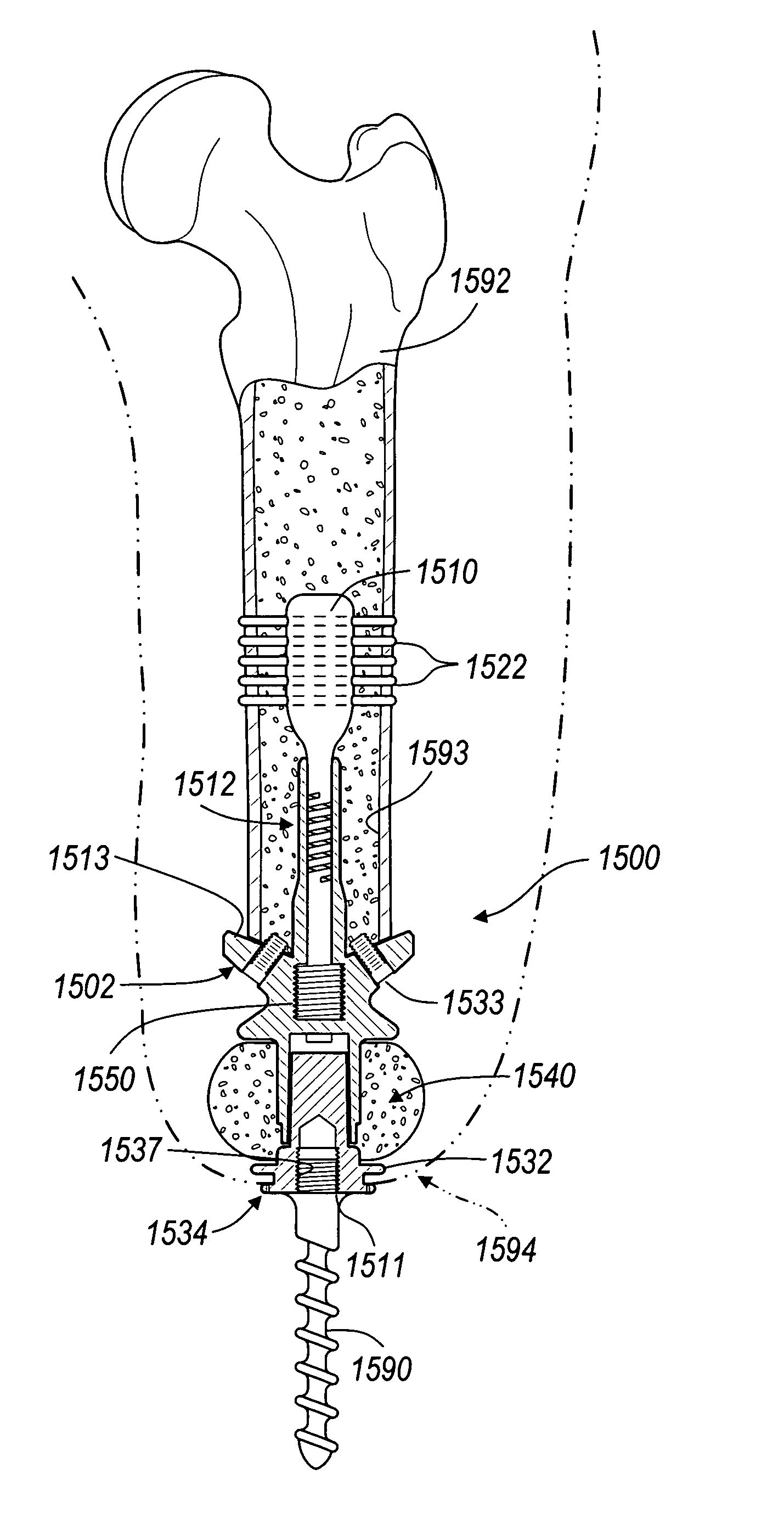
[0125]In the version of the present invention shown in FIG. 15, the first intramedullary cavity 204 is an enlarged natural intramedullary cavity of the bone. The first intramedullary cavity 204 thus substantially coincides in its longitudinal axis with that of the natural intramedullary cavity of the bone. The bone attachment assembly 200 may also be inserted within the natural intramedullary cavity of the bone, without further enlargement, where suitable.

[0126]The bone attachment assembly 200 is constructed of a suitable biocompatible material, such as those previously described. It will be appreciated that all of the materials set forth in the second embodiment herein may be made from the same materials as previously described or any other suitable materials. The bone attachment assembly 200 includes a main body 206 that is substantially cylindrically-shaped, and is preferably operable to be positioned upon a surface of the first remaining bone portion 202. To provide means for co...

third embodiment

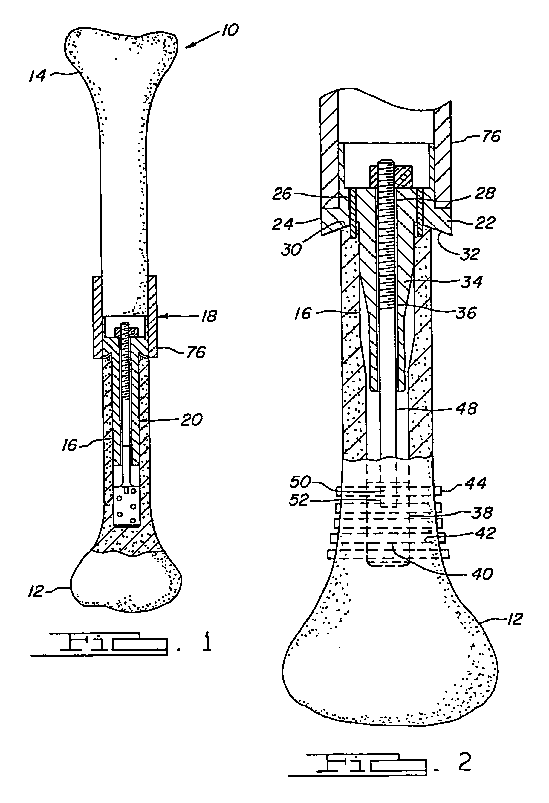
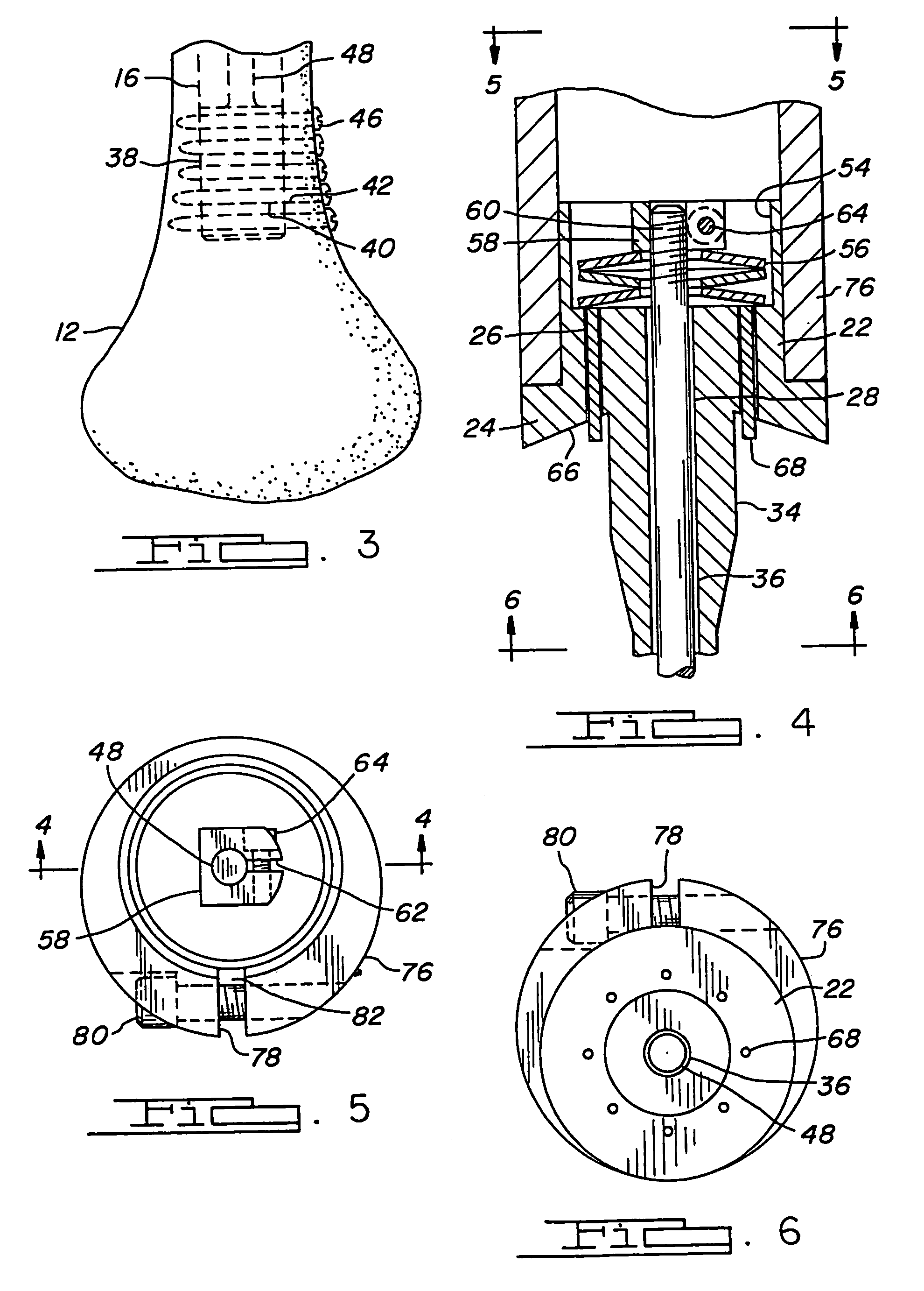
[0156]Referring now to FIGS. 27–31, there is shown a first version of the present invention. In this embodiment, the bone attachment assembly is provided with a sleeve for inhibiting tilting of the compliant section of the assembly in a non-axial direction. This sleeve is preferably an integral extension connected to the main body of the assembly. The bone attachment assembly also includes several additional variations of anchor bodies, which may be secured within a remaining bone portion in different ways. In addition, in this embodiment, the compliant section is provided as an integral extension upon the anchor body.

[0157]FIG. 27 is an exploded elevational view of a bone attachment assembly, generally at 500, in a modular form. The bone attachment assembly 500 includes a main body 502 having a shoulder portion 504 and an interface surface 506, in similar manner as before. The interface surface 506 is shown to be disposed at an angle relative to the longitudinal axis of the main bo...


PUM


Abstract

A fixation device and method for attaching an external prosthesis to a bone. The fixation device includes a main body having a compliant portion operable to be expanded and contracted. The main body has a first end fixedly retained in the bone and a second end coupled to an extension for receiving the external prosthesis. The main body and the extension define respectively first and second engagement surfaces for constraining a bone graft therebetween.

Description

CROSS REFERENCE TO RELATED APPLICATIONS[0001]This application is a continuation-in-part of U.S. Ser. No. 10 / 305,620, filed Nov. 27, 2002 now U.S. Pat. No. 6,712,855, which is a continuation of U.S. Ser. No. 09 / 776,584, filed Feb. 2, 2001, now U.S. Pat. No. 6,508,841 which is a continuation of U.S. Ser. No. 09 / 003,061, filed Jan. 5, 1998, now U.S. Pat. No. 6,197,065, which is a continuation-in-part of U.S. Ser. No. 08 / 535,532, filed Sep. 28, 1995, now abandoned, which is a continuation-in-part of U.S. Ser. No. 08 / 146,510, filed Nov. 1, 1993, now abandoned. The disclosures of the above applications are incorporated herein by reference.INTRODUCTION[0002]In prosthetic segmental bone replacements, it is sometimes necessary to replace a portion of a long bone to correct various types of bone injury such as those caused by bone tumors, osteoarthritis, fracture dislocations, rheumatic arthritis, and aseptic or a vascular bone necrosis. In these types of surgical procedures, it is necessary ...

Claims


Application Information

Patent Timeline
IPC IPC(8): A61F2/60A61B17/16A61B17/17A61B17/72A61F2/00A61F2/28A61F2/30A61F2/36A61F2/50A61F2/78
CPCA61B17/164A61B17/1725A61B17/7216A61F2/28A61F2/3601A61F2/3607A61B17/1668A61B2017/1602A61F2002/30535A61F2220/0033A61F2250/0058
Inventor MAY, BRIAN MWHITE, JOHN RO'DONNELL, RICHARD J
Owner BIOMET MFG CORP
Why Eureka
Try Eureka